Sign In
Upload
Manuals
Brands
Dettson Manuals
Furnace
Chinook C60-M-S
User Manuals: Dettson Chinook C60-M-S Gas Furnace
Manuals and User Guides for Dettson Chinook C60-M-S Gas Furnace. We have
1
Dettson Chinook C60-M-S Gas Furnace manual available for free PDF download: Installation Manual And Owner's Manual
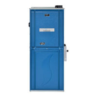
Dettson Chinook C60-M-S Installation Manual And Owner's Manual (65 pages)
High efficiency modulating and multiposition condensing gas furnace
Brand:
Dettson
| Category:
Furnace
| Size: 3 MB
Table of Contents
Table of Contents
2
1 Safety Regulation
6
Safety Labeling and Warning Signs
6
Important Information
6
Detection Systems
6
2 Introduction
8
Codes and Standards
9
1- Safety
9
2- General Installation
9
3- Combustion and Air Ventilation
9
4- Duct Systems
9
5- Acoustical Lining and Fibrous Glass Duct
9
6- Gas Piping and Pipe Pressure Testing
9
7- Electrical Connections
9
Electrostatic Discharge
9
Location
9
2- Location Relative to Cooling Equipment
10
3 Combustion Air and Ventilation
10
Introduction
10
1- Direct Vent (2 Pipe Applications)
10
Figure 2 Installation in a Garage
10
Figure 3 Prohibited Installation
10
Table 1 Minimum Clearance to Combustible Material for All Units
10
Table 2 Loose Parts List
10
2- Non Direct Vent (1 Pipe) Applications
11
3- Ventilated Combustion Air Applications
11
Connecting to Furnace
11
Figure 4 Dimensional Drawing
11
1- Combustion Air Piping
12
2- Exhaust Vent Piping
12
Figure 5 Vent Coupling and Adapter with Gaskets
12
Figure 6 Vent Termination
12
4 Installation
13
Upflow Orientation
13
Figure 7 Drain Trap
13
Figure 8 Left Side Condensate Drain Connection
13
Figure 9 Right Side Condensate Drain Connection
13
1- Right Side Condensate Drain Connection
14
2- Left Side Condensate Drain Connection
14
Down Flow Orientation
14
1- down Flow Condensate Drain Connection
14
2- Downflow Venting Drainage
14
3- Condensate Box Pressure Switch
14
Horizontal Right Orientation
14
Horizontal Right Condensate Drain Connection
14
Figure 10 down Flow Orientation
14
Figure 11 Condensate Pressure Switch
14
Horizontal Right Vent Drainage
15
Condensate Box Pressure Switch
15
Horizontal Left Orientation
15
Horizontal Left Condensate Drain Connection
15
Figure 12 Horizontal Right Drain Trap Position
15
Figure 13 Horizontal Right Condensate Tubing
15
Figure 14 Pressure Switch Assembly
15
2- Condensate Box Pressure Switch
16
5 Duct Installation
16
Return Air Connections
16
1- Bottom Return Air Inlet
16
2- Side Return Air Inlet
16
Filter Arrangement
16
Supply Air Ducts
16
General Requirements
16
Figure 15 Horizontal Left Condensate Drain Connection
16
Figure 16 Return Air Base
16
Duct Work Acoustical Treatment
17
6 Gas Piping
17
Table 3 Maximum Air Flow Capacity and Blower
17
Table 4 Maximum Capacity of Pipe in Ft³ of Gas/Hr
17
Gas Pipe Grommet
18
7 Electrical Connections
18
Wiring
18
Figure 17 Typical Gas Pipe Arrangement
18
Table 5 Gas Pressure
18
Table 6 Electrical Data
18
Wiring
19
Thermostats
19
Alternate Power Supply
19
Figure 18 Wiring Diagram
20
8 Venting
21
Special Venting Requirements for Installations in Canada
21
General
21
Materials
21
Direct Vent - 2 Pipes System
21
Size of the Vent and Combustion Air Pipes
21
Figure 19 Direct Venting
22
Figure 20 Multiventing
22
Combustion Air and Vent Piping Insulation Guidelines
23
Table 7 Maximum Equivalent Vent Length (Ft.)
23
Table 8 Deduction for Fitting
23
Table 9 Approved Combustion Air and Vent Pipe, Fitting and Cement Materials (U.S.A. Installation) - (in Canada All Vent Material S Shall Comply to ULC S636)
23
Installing the Vent Termination
24
1- Concentric Vent
24
2- Two Pipe Termination
24
3- Sidewall Termination
24
9 Start Up, Adjustment and Safety Check
24
To Start the Furnace
25
Lighting Instructions
25
Unit Operation Hazard
25
Setup Switches
25
Figure 21 Dip Switch Setting - S1
26
Figure 22 Dip Switch Setting - S3
26
Fault Code Reset
27
Diagnostic Features
27
Sequence of Operation
27
1- Heating Cycle Initiation
27
Figure 23 Dip Switch Setting - S4
27
Figure 24 Dip Switch - S5
27
2- Heating Cycle Response
28
3- Setting Input Rate
28
10 Thermostat
28
Non-Communicating Modulating Thermostats
28
Figure 25 Wiring Diagram for Modulating Heat (no Dual Fuel) (Non-Communicating)
28
24 VAC Thermostat (TSTAT) INPUT (J4 & J6)
29
Fuse (F1)
29
120 VAC Terminals
29
Induced Draft Motor (Inducer) Control Output (E8)
29
Electronic Air Cleaner (E.A.C.) Output (E-103)
29
Stepper Gas Valve Control
29
Figure 26 Fully Modulating - Typical Dual Fuel Application - Single Stage Heat Pump (Non-Communicating)
29
Pin Mate-V-Lok Connector (J1)
30
Communicating ECM Motor Communications (Control) Connection (E114)
30
Communications L.e.D.'s (Light Emitting Diodes)
30
Memory Card
30
Figure 27 15-Pin Connector; J1 with Pin Designations
30
Dipswitch
32
1- S1 - Heat Air Flow Adjustment
32
2- S3-1 and S3-2 - Cooling Airflow Select
32
3- S3-3 and S3-4 - Cooling and Heat Pump Air Flow Adjustment
32
4- S4 - Heat Rise Adjust
32
Table 10 S4-2 and S4-3 Mode Selection Setting
32
5- S5 - Cooling
33
11 User's Information Manual
33
Table 11 Cooling Airflow Selections for Non-Communicating Condensers
33
Operating Your Furnace
34
Lighting Instructions
34
Shutting down the Furnace
34
To Turn off Gas to the Furnace
34
Maintenance of Your Furnace
34
Figure 28 Control Switch Modulating Valve
34
Combustion and Ventilation Air
35
Return Air
35
Filter Location
35
1- Cleaning/Replacing the Filter
35
Lubrication
35
Burner Flame
35
Condensate Collection and Disposal System
35
Rollout Switch
35
Safety Interlock Switch
35
Figure 29 Typical Flame Appearance
35
Repair Parts
36
Dual Seven Segment Display
36
Fault Code Buffer
36
1- Clearing Diagnostic Fault Codes from the Buffer
36
Active Fault Codes
36
Table 12 Normal Operation Codes/Messages
36
Table 13 Fault Code
36
Data
37
FAULT CODE 1 - D1 no Shared Data
37
FAULT CODE 2 -D3 Airflow Mismatch
37
FAULT CODE 3 - D4 Memory Card
38
FAULT CODE 4 - D5 Card Hardware Conflict
38
FAULT CODE 5 - D6 Blower Horsepower Conflict
39
FAULT CODE 6 - D7 Blower Manufacturer Conflict
39
FAULT CODE 7 - D8 Old Shared Data
40
FAULT CODE 8 - H Gas Heat on - no V
41
FAULT CODE 9 - 10 Ignition 1 Hour Retry
42
FAULT CODE 10 - 11 Failed Ignition
43
FAULT CODE 11- 12 Low Flame Sense
44
FAULT CODE 12- 13 Flame Lost
45
FAULT CODE 13 - 16 Igniter Fail
46
FAULT CODE 14 - 14 Unexpected Flame
46
FAULT CODE 15 - 22 Main Limit Open
47
FAULT CODE 16 - 26 Line Neutral Reverse
47
FAULT CODE 17 - 33 MRLC (Manually Reset Limit Control) OPEN
48
FAULT CODE 18 - 44 LPC (Low Pressure Control (Switch)) Closed
49
FAULT CODE 19 - 46 LPC (Low Pressure Control (Switch)) Open
50
FAULT CODE 20- 55 HPC (High Pressure Control (Switch)) CLOSED
51
FAULT CODE 21 - 57 HPC (High Pressure Control (Switch)) OPEN
52
FAULT CODE 22 - 60 Blower Fault - Running
53
FAULT CODE 23 - 61 Blower Fault - Not Running
53
FAULT CODE 24 - 66 Blower Overspeed
54
FAULT CODE 25 - 68 no Blower Communication
54
FAULT CODE 26 - 71 no Inducer Communications
55
FAULT CODE 27 - 77 no Gas Valve Feedback
55
FAULT CODE 28 - 93 Control Fault
56
Figure 30 Exploded View - Modulating
57
Table 14 Part List - Modulating - ECM 3.0
59
Advertisement
Advertisement
Related Products
Dettson C60-2-D
Dettson C60-1-D
Dettson C60-2-V
Dettson Chinook C60-M-V
Dettson Chinook C60-1-X
Dettson C105-1-D
Dettson C45-2-D
Dettson C120-2-V
Dettson Chinook C15-M-S
Dettson Chinook C30-M-V
Dettson Categories
Furnace
Boiler
Air Conditioner
Thermostat
Heat Pump
More Dettson Manuals
Login
Sign In
OR
Sign in with Facebook
Sign in with Google
Upload manual
Upload from disk
Upload from URL