Sign In
Upload
Manuals
Brands
Design Analysis Manuals
Data Loggers
H-500XL
User Manuals: Design Analysis H-500XL Data Logger
Manuals and User Guides for Design Analysis H-500XL Data Logger. We have
1
Design Analysis H-500XL Data Logger manual available for free PDF download: Owner's Manual
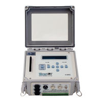
Design Analysis H-500XL Owner's Manual (272 pages)
XL Series WaterLog series Data Logger / Data Collection Platform
Brand:
Design Analysis
| Category:
Data Loggers
| Size: 6 MB
Table of Contents
Table of Contents
3
Chapter 1 Introduction
11
Introduction to the XL™ Series Data Logger
11
Unpacking the XL™ Series Data Logger
12
Modes of Operation
12
Sensor Mode
13
Data Logger / DCP Master Mode
13
Operation Using Auxiliary Outputs
13
Operation with the H-355 Gas Purge System (Bubbler)
14
About this Manual
14
Advanced Manual Sections
14
Web
14
Chapter 2 Hardware Options and Installation
15
Mechanical Mounting
15
Front Panel Description
15
Earth Ground Lug
16
Pressure Reference Port (Vent)
16
Pressure Port (Input)
16
GOES Antenna Output
17
GPS Antenna Connector
17
Sample Installation for the Conoflow System
18
Making the Pressure Connection to the H-355 Bubbler
19
Bubbler / Aux Port
20
Ports
21
Analog Input Section
22
Analog Input Channels
22
Analog Grounds
22
Switched +5 Volt Reference Excitation
23
Wind Speed Input (AC Frequency Input)
23
Event Counter Input
24
To 20 Milliamp Output
25
Digital I/O 1 and 2
26
SDI-12 Section
27
Power Connections
28
Testing the Installation
28
Hardware Revision Detection
29
Chapter 3 Using the Built in Keypad / Display
31
Overview
31
Keypad/Display Operation
31
Familiarization
36
Main Menu Description
37
Chapter 4 Using the PC Menu Interface Operation
43
PC Menu Interface
43
PC Menu General Operations
44
Main Menu Screen
45
Chapter 5 General System Options
47
Overview
47
System Setup
47
Time Sync Options
51
Advanced System Setup Options
54
Chapter 6 Serial Port Options
59
Introduction
59
Serial Port Menus
59
Serial Port Hardware Description
64
Serial Port Functions
64
Chapter 7 System Configuration Files
67
Overview
67
Configuration Files Menus
67
Sample Configuration File
69
Chapter 8 System Status Menus / Optioons
75
Status Options Overview
75
Status Menus
75
Status Screen Operations
76
Chapter 9 Scanning Options
85
Introduction
85
Scanning Menus
85
Scanning Options
85
Chapter 10 Stage Menus / Options
93
Stage Options (H-350XL / H-510XL Only)
93
Remote Stage Setup Overview
93
Remote Stage Menus
93
Remote Stage Options
93
Chapter 11 Analog Inputs / 5 Volt Excitation
95
Analog Inputs Overview
95
Analog Menus
95
Analog Options
96
Analog Input Connections
98
Analog Inputs and Analog Ground Connections
98
Switched +5.00 Volt Reference Excitation
99
Analog Input Setup Examples
99
Two Point Calibration Basics
101
Chapter 12 Digital I/O
103
Digital I/O Overview
103
Digital I/O Menus
103
Digital I/O Options
104
Quadrature Shaft Encoder Options
109
Chapter 13 Counter and Frequency Inputs
111
Introduction
111
Counter and Frequency Menus
111
Counter Options
112
Frequency Options
115
Chapter 14 SDI-12 Operations
117
Overview
117
Transparent Mode and Full Screen Mode
117
Data Logger Mode
122
Sensor Mode
125
H310 Setup
128
H330 / H331 Setup
130
Sensor Mode Supported Commands
132
Command and Response Protocol
133
Standard SDI-12 Command Set
134
Send Acknowledge Command
134
Send Identification Command
135
Measure Command
136
Initiate Verify Command
137
Send Data Command
139
Change Sensor Address
139
Extended SDI-12 Command Set
140
Write "User Units Slope" Command
141
Write "User Units Offset" Command
141
Read User Units Slope" Command
141
Read "User Units Offset" Command
144
Chapter 15 Logging Options
145
Logging Overview
145
Logging Options Menu
145
Logging Options
145
Chapter 16 Operation with the GOES Radio
157
Introduction
157
GOES Radio Data Connection
157
GOES Radio Types
157
Configuring the GOES Radio, General Options
159
GOES Self Timed Options
166
GOES Random Options
180
GOES Diagnostics
184
GOES Radio Setup Example
187
GOES Binary Data
188
GOES Four Byte Pseudo-Binary Lookup Table
190
Common GOES Terms
191
Julian Day Tables
193
GOES Downlink Message Header Basics
195
Chapter 17 ALERT Radio Operation
199
Introduction
199
ALERT Menus
199
ALERT Options
200
Special Cases for ALERT Transmissions
206
Chapter 18 4 to 20 Milliamp Output
207
Introduction
207
To 20 Milliamp Menus
207
To 20 Milliamp Options
207
To 20 Hardware Connections / Wiring
210
Chapter 19 Alarm Call out
211
Overview
211
Alarm Call out Menus
211
Chapter 20 Data Card Options
217
Data Card Options
217
Data Card / Memory Options
218
Chapter 21 Operation with the H-355 "Smart Gas" System
227
Menus
227
Introduction to the H-355
227
Options
228
Configuration Drawing
233
Chapter 22 Functions
235
Introduction
235
Function Menu
235
Chapter 23 XL-Basic Programming Guide
248
General Purpose Variables
248
Standard Input Variables
249
Read Only Variables
250
Math Functions
251
XL-Basic Command Summary
252
Creating XL-Basic Programs
264
XL-Basic Menu Screens
264
Example Program #1
266
Example Program #2
267
Chapter 24 Maintenance / Troubleshooting
269
Maintenance
269
Troubleshooting
269
Appendix A XL Series Specifications
271
Advertisement
Advertisement
Related Products
Design Analysis H-350XL
Design Analysis H-510XL
Design Analysis H-522
Design Analysis WaterLOG H-3521
Design Analysis Categories
Transducer
Data Loggers
More Design Analysis Manuals
Login
Sign In
OR
Sign in with Facebook
Sign in with Google
Upload manual
Upload from disk
Upload from URL