Sign In
Upload
Manuals
Brands
Delta Electronics Manuals
Media Converter
VFD-EL series
Delta Electronics VFD-EL series Manuals
Manuals and User Guides for Delta Electronics VFD-EL series. We have
1
Delta Electronics VFD-EL series manual available for free PDF download: User Manual
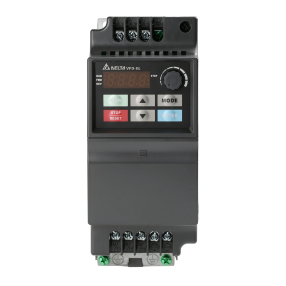
Delta Electronics VFD-EL series User Manual (182 pages)
Sencorless vector control micro drive
Brand:
Delta Electronics
| Category:
Media Converter
| Size: 9 MB
Table of Contents
Preface
2
Safety Information
2
Table of Contents
3
Receiving and Inspection
8
Model Explanation
8
Nameplate Information
8
Chapter 1 Introduction
8
Series Number Explanation
9
Drive Frames and Appearances
9
Internal Structure
9
Product View
9
RFI Jumper
10
Remove Instructions
10
Preparation for Installation and Wiring
11
Ambient Conditions
11
Minimum Mounting Clearances
11
DC-Bus Sharing: Connecting the DC-Bus of the AC Motor Drives in
12
Dimensions
13
General Wiring Information
14
Chapter 2 Installation and Wiring
14
Wiring
15
Wiring for NPN Mode and PNP Mode
17
NPN Mode Without External Power
17
NPN Mode with External Power
17
PNP Mode Without External Power
17
External Wiring
19
Main Circuit Connection
20
Mains Power Terminals
20
Output Terminals for Main Circuit
20
Terminals [+, -] for Connecting Brake Resistor
20
Main Circuit Terminals
21
Control Terminals
22
Analog Inputs
23
Digital Inputs
23
The Specification for the Control Terminals
24
Description of the Digital Keypad
26
Chapter 3 Keypad and Start up
26
How to Operate the Digital Keypad
27
Reference Table for the 7-Segment LED Display of the Digital Keypad
27
Operation Method
28
Trial Run
29
Chapter 4 Parameters
30
Summary of Parameter Settings
31
Basic Parameters
33
Operation Method Parameters
35
Output Function Parameters
37
Input Function Parameters
39
Multi-Step Speed Parameters
41
Protection Parameters
42
Motor Parameters
44
Special Parameters
45
Communication Parameters
46
PID Control Parameters
47
Parameter Settings for Applications
50
Description of Parameter Settings
54
Rated Current Display of the AC Motor Drive
54
Parameter Reset
54
Start-Up Display Selection
54
Content of Multi-Function Display
55
User Defined Coefficient K
55
Password Input
55
Password Set
55
Control Mode
56
Password Decode Flow Chart
56
50Hz Base Voltage Selection
57
User Defined Value (Correspond to Max. Operating Frequency)
57
Decimal Place of User-Defined Value
57
Maximum Output Frequency (Fmax)
58
Maximum Voltage Frequency (Fbase)
58
Maximum Output Voltage (Vmax)
58
MID-Point Frequency (Fmid)/MID-Point Voltage (VMID)
58
Output Frequency Lower Limit
59
Acceleration Time/Deceleration Time
59
Accel/Decel Time Unit
59
Jog Acceleration/Deceleration Time
60
Jog Frequency
60
Auto-Acceleration / Deceleration
61
Acceleration S-Curve
61
Deceleration S-Curve
61
Simple Positioning Stop Frequency
61
Delay Time of Simple Positioning
62
Source of First Operation Command
65
Combination of the First and Second Master Frequency Command
65
Stop Method
65
PWM Carrier Frequency Selections
66
Motor Direction Control
67
The Source of Power-On Command and Running Command Modifies
67
Loss of ACI Signal (4-20Ma)
69
Up/Down Mode
69
Accel/Decel Rate of Change of UP/DOWN Operation with Constant Speed
69
Keypad Frequency Command/Communication Frequency Command
69
The Selections for Saving Keypad or Communication Frequency Command
70
Display the Master Freq Command Source
70
Display the Operation Command Source
70
Initial Frequency Setpoint (for Keypad & RS485)
70
Group 3: Output Function Parameters
72
Multi-Function Output Relay
72
Desired Frequency Attained
73
MO 23 Description
73
Analog Output Signal (AFM)
74
Analog Output Gain
74
Terminal Count Value
74
Preliminary Count Value
74
EF Active When Terminal Count Value Attained
75
Fan Control
75
Brake Release Frequency
75
Brake Engage Frequency
75
Display the Status of Relay
76
Group 4: Input Function Parameters
77
Keypad Potentiometer Bias Polarity
77
Keypad Potentiometer Negative Bias, Reverse Motion Enable/Disable
77
Use of 0-5V Potentiometer Range Via Gain Adjustment
78
Use of Negative Bias in Noisy Environment
78
Use of Negative Bias in Noisy Environment and Gain Adjustment
78
Use of 0-10V Potentiometer Signal to Run Motor in FWD/REV Direction
78
Maximum ACI Frequency
79
Maximum ACI Current
79
Minimum ACI Frequency
79
Minimum/Maximum AVI Voltage
79
Multi-Function Input Terminal 2-Wire/ 3-Wire Operation Control Modes
80
Multi-Function Input Terminal
81
Multi-Function Input Contact Selection
83
Digital Terminal Input Debouncing Time
83
Display the Status of Multi-Function Input Terminal
84
Internal/External Multi-Function Input Terminals Selection
84
Internal Terminal Status
85
Group 5: Multi-Step Speeds Parameters
86
Multi-Speed Via External Terminals
86
Group 6: Protection Parameters
88
Over-Voltage Stall Prevention
88
Over-Current Stall Prevention During Acceleration
88
Over-Current Stall Prevention During Operation
89
Over-Torque Detection Mode
89
Over-Torque Detection Level
89
Over-Torque Detection Time
90
Electronic Thermal Overload Relay Selection
90
Electronic Thermal Characteristic
90
Fifth most Recent Fault Record
90
Group 7: Motor Parameters
92
Motor Rated Current
92
Motor Parameters Auto Tuning
92
Motor Line-To-Line Resistance R1 (Motor 0)
92
Motor Rated Slip (Motor 0)
93
Slip Compensation Limit
93
Torque Compensation Time Constant
93
Slip Compensation Time Constant
93
Treatment of the Motor PTC Overheat
94
Input Debouncing Time of the PTC Protection
95
Group 8: Special Parameters
96
Start-Point for DC Brake
96
Momentary Power Loss Operation Selection
96
Base Block Speed Search
96
Baseblock Time for Speed Search (BB)
97
Current Limit for Speed Search
98
Skip Frequency 3 Lower Limit
98
Auto Restart after Fault
98
Auto Reset Time at Restart after Fault
98
Automatic Energy-Saving
99
Automatic Voltage Regulation (AVR)
99
Compensation Coefficient for Motor Instability
99
Level of Pre-Heat DC Current
99
Pre-Heat DC Current Duty Cycle
100
Group 9: Communication Parameters
102
Transmission Speed
102
Transmission Fault Treatment
102
Communication Protocol
102
Communication Data Frame
104
Address (Communication Address)
105
Function (Function Code) and DATA (Data Characters)
105
Check Sum
107
Address List
108
Communication Program of PC
111
The Explanation of Exception Codes
111
Response Delay Time
112
KPC-CC01 Keypad Enable / Disable
112
Group 10: PID Control
113
PID Set Point Selection
113
Input Terminal for PID Feedback
113
Proportional Gain (P)/Integral Time ( I )
113
Derivative Control (D)
114
Primary Delay Filter Time
114
PID Feedback Signal Detection Time
114
Treatment of the Erroneous Feedback Signals (for PID Feedback Error)
114
Gain over the PID Detection Value
115
Detection Time of PID Feedback
115
Wakeup Frequency
115
PID Offset
116
Feedback of PID Physical Quantity Value
116
PID Calculation Mode Selection
116
Treatment of the Erroneous PID Feedback Level
117
Detection Time of Set Point Deviation Level
117
Offset Level of Liquid Leakage
117
Time Setting for Liquid Leakage Change
117
Multi-Pump Control Mode
118
Multi-Pump ID
118
Multi-Pump’s Fixed Time Circulation Period
118
Frequency to Start/Stop Switching Pumps
118
Time Detected When Pump Reaches the Stopping Frequency
119
Pump’s Frequency at Time out (Disconnection)
119
Pump’s Error Handling
119
Selection of Pump’s Startup Sequence
119
Running Time of Multi-Pump under Alternative Operation
120
Assign the Setting of Pr10.12[Pid Feedback Level ]
120
Number of Times to Restart When PID Error Is Occurred
120
VFD-EL Multi Pumps SOP
121
Accessories for Multi-Pump under Alternative Operation
122
Wiring Method When the System Is under Multi-Pump Operation
122
Related Parameters When Pr10.35=1
123
Related Parameters When Pr10.35=2
129
Over Current (OC)
134
Chapter 5 Troubleshooting
134
Ground Fault
135
Over Voltage (OV)
135
Low Voltage (Lv)
136
Over Heat (OH1)
137
Overload
137
Keypad Display Is Abnormal
138
Phase Loss (PHL)
138
Motor Cannot Run
139
Motor Speed Cannot be Changed
140
Motor Stalls During Acceleration
141
The Motor Does Not Run as Expected
141
Electromagnetic/Induction Noise
142
Environmental Condition
142
Affecting Other Machines
142
Chapter 6 Fault Code Information and Maintenance
144
Maintenance and Inspections
147
Reset
147
Specifications
152
Accessories
154
B.1 All Brake Resistors & Brake Units Used in AC Motor Drives
154
Appendix a Specifications
156
Appendix B Accessories
156
B.1.1 Dimensions and Weights for Brake Resistors
156
B.2 no Fuse Circuit Breaker Chart
158
B.3 Fuse Specification Chart
159
B.4 AC Reactor
160
B.4.3 Applications
161
B.5 Zero Phase Reactor (RF220X00A)
162
B.6 Remote Controller RC-01
163
Remote Controller RC-01 Data
163
B.7 Pu06
164
Description of the Digital Keypad VFD-PU06
164
Explanation of Display Message
164
PU06 Data
164
B.7.3 Operation Flow Chart
165
Operation Flow Chart of the Digital Keypad
165
Devicenet Communication Module
166
B.8 Fieldbus Modules
166
B.8.1.3 Power Supply
167
Lonworks Communication Module
167
B.8.2.3 Specifications
168
B.8.3 Profibus Communication Module (CME-PD01)
169
B.8.3.2 Dimensions
170
PROFIBUS Address
170
B.8.4 CME-COP01 (Canopen)
171
B.8.4.3 Components
172
B.8.4.4 LED Indicator Explanation & Troubleshooting
173
EMC Earthing Plate for Shielding Cable
174
B.9.2 DIN Rail: MKEL-DRA (Only for Frame A)
175
How to Select the Right AC Motor Drive
176
Capacity Formulas
177
Appendix C How to Select the Right AC Motor Drive
177
C.2 General Precaution
178
Parameter Settings Note
178
C.3 How to Choose a Suitable Motor
179
Motor Torque
180
Advertisement
Advertisement
Related Products
Delta Electronics VFD007F43H
Delta Electronics VFD075F43H
Delta Electronics VFD150F43A
Delta Electronics VFD185F23A
Delta Electronics VFD2200F43A
Delta Electronics VFD185V23A/43A-2
Delta Electronics VFD370V43A-2
Delta Electronics VFD300VL43A
Delta Electronics VFD004EL11A
Delta Electronics VFD055F43B-G
Delta Electronics Categories
Power Inductor
Power Supply
Computer Hardware
Fan
Transceiver
More Delta Electronics Manuals
Login
Sign In
OR
Sign in with Facebook
Sign in with Google
Upload manual
Upload from disk
Upload from URL