Sign In
Upload
Manuals
Brands
Delta Manuals
Servo Drives
ASD-A2-1F43 Series
Delta ASD-A2-1F43 Series Manuals
Manuals and User Guides for Delta ASD-A2-1F43 Series. We have
2
Delta ASD-A2-1F43 Series manuals available for free PDF download: User Manual, Instruction Sheet
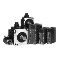
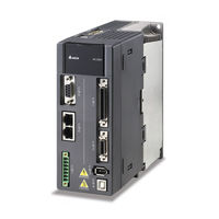
Delta ASD-A2-1F43 Series User Manual (753 pages)
High Resolution AC Servo Drive for Network Communication Applications
Brand:
Delta
| Category:
Servo Drives
| Size: 13 MB
Table of Contents
Revision September
2
Table of Contents
6
Chapter 1 Unpacking Check and Model Explanation
16
Unpacking Check
16
Model Explanation
19
Nameplate Information
19
Model Name Explanation
20
Servo Drive and Servo Motor Combinations
22
Series
22
Series
23
Servo Drive Features
24
Series
24
Series
27
Chapter 2 Installation and Storage
30
Installation Notes
30
Storage Conditions
30
Installation Conditions
31
Installation Procedure and Minimum Clearances
32
Circuit Interrupter and Fuse Current Recommended Value
36
EMI Filter Selection
37
Regenerative Resistors
42
Chapter 3 Connections and Wiring
52
Connecting to Peripheral Devices
52
Servo Drive Connectors and Terminals
53
Wiring Methods
55
Motor Power Cable Connector Specifications
57
Encoder Connector Specifications
59
Cable Specifications for Servo Drive
63
Connecting to Peripheral Devices
65
Servo Drive Connectors and Terminals
66
Wiring Methods
69
Motor Power Cable Connector Specifications
70
Encoder Connector Specifications
72
Cable Specifications for Servo Drive
74
Basic Wiring
76
Series
76
Series
79
Input / Output Interface Connector -CN1
81
CN1 Terminal Identification
81
Signals Explanation of Connector CN1
83
User-Defined DI and DO Signals
96
Wiring Diagrams of I/O Signals (CN1)
97
Application: Using CN1 Convenient Connector for Wiring
107
Encoder Connector CN2
110
Serial Communication Connector CN3
114
CN3 Terminal Layout and Identification
114
Connection between Pc/Keypad and Connector CN3
115
Serial Communication Connector CN4 (USB)
116
Position Feedback Signal Connector CN5 (for Full-Closed Loop)
117
Canopen Communication Connector CN6
118
Extension Digital Input Connector CN7
120
Position (PT) Control Mode
121
Position (PR) Control Mode
122
Speed Control Mode
123
Torque Control Mode
124
Canopen Communication Mode
125
Standard Connection Example
126
Position (PT) Control Mode
126
Position (PR) Control Mode
127
Speed Control Mode
128
Torque Control Mode
129
Canopen Communication Mode
130
Chapter 4 Display and Operation
132
Description of the Digital Keypad
132
Display Flowchart
133
Status Display
134
Save Setting Display
134
Decimal Point Display
134
Fault Message Display
134
Polarity Setting Display
134
Monitor Setting Display
135
General Function Operation
138
Fault Code Display Operation
138
JOG Operation
138
Force Output Control Operation
139
DI Diagnosis Operation
140
DO Diagnosis Operation
141
Chapter 5 Trial Run and Tuning Procedure
142
Inspection Without Load
142
Applying Power to the Drive
144
JOG Trial Run Without Load
148
Speed Trial Run Without Load
150
Position Trial Run Without Load
152
Tuning Procedure
154
Tuning Flowchart
155
Load Inertia Estimation Flowchart
156
Auto Mode Tuning Flowchart
157
Semi-Auto Mode Tuning Flowchart
159
Limit of Load Inertia Estimation
161
Mechanical Resonance Suppression Method
163
Relationship between Tuning Modes and Parameters
164
Gain Adjustment in Manual Mode
165
Chapter 6 Control Modes of Operation
168
Control Modes of Operation
168
Position Control Mode
170
Command Source of Position (Pt) Control Mode
171
Command Source of Position (Pr) Control Mode
175
Structure of Position Control Mode
176
S-Curve Filter for Position Control
177
Electronic Gear Ratio
182
Low-Pass Filter
182
Timing Chart of Position (Pr) Control Mode
183
Position Loop Gain Adjustment
184
Low-Frequency Vibration Suppression
186
Speed Control Mode
192
Command Source of Speed Control Mode
192
Structure of Speed Control Mode
193
Smoothing Strategy of Speed Control Mode
194
Analog Speed Input Scaling
199
Timing Chart of Speed Control Mode
200
Speed Loop Gain Adjustment
200
Resonance Suppression
207
Torque Control Mode
215
Command Source of Torque Control Mode
215
Structure of Torque Control Mode
216
Smoothing Strategy of Torque Control Mode
217
Analog Torque Input Scaling
218
Control Modes Selection
220
Speed / Position Control Mode Selection
221
Speed / Torque Control Mode Selection
222
Torque / Position Control Mode Selection
223
Others
224
Speed Limit
224
Torque Limit
224
Analog Monitor
225
Electromagnetic Brake
229
Chapter 7 Motion Control Functions
232
Motion Control Functions
232
System Information
232
Monitoring Variables
233
Data Array
239
Motion Axes
243
PR Mode
244
Comparison
244
Pulse of User Unit
245
Position Registers
245
Homing Function
247
Triggering Prs
248
Parameter Settings
250
Motion Commands
258
Sequence
259
Electronic Cam (E-Cam)
262
Capture Function
272
Compare Function
274
Definition
278
Chapter 8 Servo Parameters
278
Parameter Summary
279
Parameters List by Group
279
Parameters List by Function
297
Detailed Parameter Listings
310
Group 0: P0-XX Monitor Parameters
310
Group 1: P1-XX Basic Parameters
337
Group 2: P2-XX Extension Parameters
384
Group 3: P3-XX Communication Parameters
428
Group 4: P4-XX Diagnosis Parameters
436
Group 5: P5-XX Motion Control Parameters
449
Group 6: P6-XX Pr Path Definition Parameters
511
Group 7: P7-XX Pr Path Definition Parameters
548
Table 8.A Input Function Definition
558
Table 8.B Output Function Definition
567
Chapter 9 Communications
576
RS-232 Communication Hardware Interface
576
Communication Parameters
578
MODBUS Communication Protocol
582
Communication Parameter Write-In and Read-Out
594
Chapter 10 Troubleshooting
596
Servo Drive Fault Messages Table
596
Canopen Communication Fault Messages Table
599
Motion Control Fault Messages Table
601
Absolute System Fault Messages Table
604
Potential Cause and Corrective Actions
605
Clearing Faults
627
Chapter 11 Specifications
636
Specifications of Servo Drive (ASDA-A2 Series)
636
ASDA-A2 220V Series
636
ASDA-A2 400 Series
639
Specifications of Servo Motors (ECMA Series)
642
ECMA 220V Series
642
ECMA 400 Series
648
Servo Motor Speed-Torque Curves (T-N Curves)
652
Series
652
Overload Characteristics
654
Dimensions of Servo Drive
656
Series
656
Series
663
Dimensions of Servo Motor (ECMA Series)
667
Series
667
Series
673
Chapter 12 Absolute System
678
Backup Battery Boxes
679
Specifications
679
Battery Box Dimensions
681
Connection Cables for Absolute Encoder
682
Battery Box Cords
683
Installation
684
Connection Examples
684
How to Install a Battery
687
How to Replace a Battery
688
System Initialization Procedure and Operation
691
System Initialization Procedure
691
Pulse Counting
692
PUU Counting
693
Use Digital Inputs/Outputs to Initialize an Absolute System
695
Use Parameters to Initialize an Absolute System
696
Use Digital Inputs/Outputs to Read the Absolute Coordinate Data
696
Use Parameter to Read the Absolute Coordinate Data
700
Related Parameters for Absolute System
701
Digital Input (DI) Function Definition (for Absolute System)
707
Digital Output (DO) Function Definition (for Absolute System)
708
Fault Messages for Absolute System
709
Potential Cause and Corrective Actions
710
Related Monitoring Variables
712
Appendix A Accessories
714
Appendix B Maintenance and Inspection
750
Advertisement
Delta ASD-A2-1F43 Series Instruction Sheet (11 pages)
Brand:
Delta
| Category:
Servo Drives
| Size: 11 MB
Advertisement
Related Products
Delta ASD-A2-1021 Series
Delta ASD-A2-1521 Series
Delta ASD-A2-1B23 Series
Delta ASD-A2-1F23 Series
Delta ASD-A2-1543 Series
Delta ASD-A2-1043 Series
Delta ASD-A2-1B43 Series
Delta ASD-A2-1021-E
Delta ASD-A2-1521-E
Delta Series
Delta Categories
Plumbing Product
Kitchen & Bath Fixtures
Bathroom Fixtures
Saw
Power Supply
More Delta Manuals
Login
Sign In
OR
Sign in with Facebook
Sign in with Google
Upload manual
Upload from disk
Upload from URL