Sign In
Upload
Manuals
Brands
DeDietrich Manuals
Boiler
C 640 Series
DeDietrich C 640 Series Manuals
Manuals and User Guides for DeDietrich C 640 Series. We have
1
DeDietrich C 640 Series manual available for free PDF download: Installation And User Manual
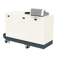
DeDietrich C 640 Series Installation And User Manual (220 pages)
High-efficiency floor-standing gas boiler with Diematic Evolution SCB-01, Diematic Evolution SCB-10
Brand:
DeDietrich
| Category:
Boiler
| Size: 14.06 MB
Table of Contents
Table of Contents
2
1 Safety
6
General Safety Instructions
6
For the Installer
6
For the End User
7
Recommendations
8
Liabilities
10
Manufacturer's Liability
10
Installer's Liability
10
User's Liability
10
2 About this Manual
11
Symbols Used in the Manual
11
3 Description of the Product
12
Boiler Types
12
Main Components
12
Dimensions and Connections C 340
14
Dimensions and Connections C 640
15
Introduction to the Controls Platform
15
Accessories and Options
16
4 Preparation of Installation
18
Installation Regulations
18
Location Requirements
18
Requirements for Water Connections
19
Requirements for the Central Heating Connections
19
Requirements for the Condensate Drain
19
Requirements for the Gas Connection
19
Requirements on the Flue Gas Discharge System
20
Classification
20
Material
22
Dimensions of Flue Gas Outlet Pipe
23
Length of the Flue and Air Supply Pipes
23
Additional Guidelines
26
Requirements for the Electrical Connections
26
Water Quality and Water Treatment
27
Process Heat Application
27
Connecting Diagrams
28
Symbols Used
28
Connection Example - 1 Direct Zone + 1 Mixing Zone + Domestic Hot Water Zone
30
Connection Example - Primary Buffer Tank + 3 Mixing Zones + Domestic Hot Water Zone
32
Connection Example - 1 Mixing Zone + 1 Direct Zone + Swimming Pool + Domestic Hot Water Zone
34
Connection Example - Low-Loss Header + 3 Mixing Zones + Domestic Hot Water Zone
37
Connection Example - 2 Boiler Cascade + Low-Loss Header + 3 Mixing Zones + Domestic Hot Water Zone
40
5 Installation
43
Positioning the Boiler
43
Mounting an Outdoor Temperature Sensor
44
Positions to be Avoided
44
Recommended Positions
44
Fitting the Outdoor Sensor
45
Flushing the System
45
Connecting the Heating Circuit
45
Connecting the Condensate Discharge Pipe
45
Connecting the Gas Pipe
46
Connecting the Air Inlet and Flue Gas Outlet
46
Electrical Connections
47
PCB Locations
47
The CB-01 Connection PCB
47
The SCB-01 Expansion PCB
49
The SCB-10 Expansion PCB
50
Connecting the Power Cable
53
Cable Routing in the Control Box Front Part
54
6 Preparation of Commissioning
55
Checklist before Commissioning
55
Filling the Installation
55
Filling the Siphon
55
Preparing the Gas Circuit
55
Control Panel Description
56
Control Panel Components
56
Description of the Home Screen
56
Description of the Main Menu
56
Meaning of the Icons in the Display
57
7 Commissioning
59
Commissioning Procedure
59
Gas Settings
59
Factory Setting
59
Adjusting to a Different Gas Type
60
Checking and Setting the Gas/Air Ratio
61
Final Instructions
64
Saving the Commissioning Settings
65
8 User Instructions
66
Accessing the User Level Menus
66
Home Screen
66
Activating Holiday Programs for All Zones
67
Heating Circuit Configuration
67
Changing the Room Temperature of a Zone
68
Definition of Zone
68
Changing the Name and Symbol of a Zone
68
Changing the Operating Mode of a Zone
69
Timer Program to Control the Room Temperature
69
Changing the Heating Activity Temperatures
71
Changing the Room Temperature Temporarily
71
Switching the Summer Mode on or off
71
Changing the Display Settings
71
Reading the Installer's Name and Phone Number
72
9 Installer Instructions
73
Accessing the Installer Level
73
Configuring the Installation at Installer Level
73
Setting the Installer Details
74
Setting the Parameters
74
Setting the Boiler Parameters When SCB-10 Is Fitted
75
Zone Functions of SCB-10
75
0-10 Volt Control with Expansion PCB
77
Setting the Heating Curve
78
Status Output on Expansion PCB
79
Commissioning the Installation
80
Chimney Sweep Menu
80
Saving the Commissioning Settings
81
Maintaining the Installation
82
Viewing the Service Notification
82
Reading out Measured Values
82
Viewing Production and Software Information
82
Changing the Domestic Hot Water Temperature Temporarily
83
Resetting or Restoring Settings
83
Resetting the Configuration Numbers CN1 and CN2
83
Carrying out an Auto Detect
84
Restoring the Commissioning Settings
84
Resetting to Factory Settings
84
Advanced Settings
84
Setting for Process Heat Application
84
Changing the ΔT Setting
85
Screed Drying
85
Cascade Control
85
10 Settings
89
Introduction to Parameter Codes
89
Changing the Parameters
89
List of Parameters
89
CU-GH13 Control Unit Settings - C 340
89
CU-GH13 Control Unit Settings - C 640
96
SCB-01 Expansion PCB Settings
102
SCB-10 Expansion PCB Settings
103
List of Measured Values
114
Control Unit Counters
114
SCB-01 Expansion PCB Counters
116
Control Unit Signals
120
SCB-01 Expansion PCB Signals
122
SCB-10 Expansion PCB Signals
123
Status and Sub-Status
144
11 Maintenance
147
Maintenance Regulations
147
Opening the Boiler
147
Standard Inspection and Maintenance Operations
147
Preparation
148
Checking the Water Quality
148
Checking the Gas Filter
148
Checking and Cleaning the Air Supply Hose
149
Checking the Air Supply Dirt Trap
149
Checking the Air Box
150
Checking the Air Pressure Differential Switch
150
Checking the Gas Leakage Monitoring (VPS)
151
Checking the Minimum Gas Pressure Switch (GPS)
152
Specific Maintenance Work
153
Cleaning the Fan, Non-Return Valve and Venturi
154
Replacing the Ionisation/Ignition Electrode
154
Cleaning the Gas Filter - 5-9 Sections Boiler
155
Cleaning the Gas Filter - 10 Sections Boiler
155
Cleaning the Burner
156
Cleaning the Heat Exchanger
157
Cleaning the Condensate Collector
157
Cleaning the Siphon
158
Assembly after Maintenance
158
Finalising Work
159
Disposal and Recycling
159
12 Troubleshooting
160
Error Codes
160
Display of Error Codes
160
Warning
160
Blocking
162
Locking
170
Error History
174
Reading out and Clearing the Error Memory
174
13 Technical Specifications
176
Homologations
176
Certifications
176
Directives
177
Factory Test
177
Electrical Diagram
177
Hydraulic Resistance
178
C 340 Technical Data
178
C 640 Technical Data
181
14 Spare Parts
185
General
185
Exploded Views
186
Parts List
191
15 Appendix
197
Erp Information
197
Product Fiche
197
EC Declaration of Conformity
197
16 Parameter Index
198
Advertisement
Advertisement
Related Products
DeDietrich C 630 ECO
DeDietrich C 610 ECO
DeDietrich C 630 Series
De Dietrich C 630 ECO 560
DeDietrich C 640 560
DeDietrich C 640 700
DeDietrich C 640 860
DeDietrich CBB 20
DeDietrich C 340 430
DeDietrich C230 ECO-A 200
DeDietrich Categories
Boiler
Hob
Oven
Ventilation Hood
Refrigerator
More DeDietrich Manuals
Login
Sign In
OR
Sign in with Facebook
Sign in with Google
Upload manual
Upload from disk
Upload from URL