Sign In
Upload
Manuals
Brands
Danfoss Manuals
Compressor
TG520 Series
Danfoss TG520 Series Compressors Manuals
Manuals and User Guides for Danfoss TG520 Series Compressors. We have
1
Danfoss TG520 Series Compressors manual available for free PDF download: Installation Manual
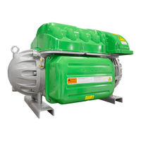
Danfoss TG520 Series Installation Manual (108 pages)
Twin-Turbine Centrifugal Compressors
Brand:
Danfoss
| Category:
Compressor
| Size: 13.01 MB
Table of Contents
Table of Contents
3
1 Introduction
9
Scope
9
Organization of this Manual
9
Table 1-1 - Application Manual Applicability
9
Document Symbols
10
Definitions
11
Table 1-2 - Definitions
11
2 Overview of the TT/TG Compressor
15
TT/TG Compressor Nomenclature
15
Refrigerant Type
15
TG Series
15
Table 2-1 - Refrigerant Used with Turbocor Compressors
15
Figure 2-1 - Compressor Nomenclature
15
Environment
16
Configurations of the TT/TG Compressor Models
16
Figure 2-2 - Major Components
16
Compressor Module
17
3 Functional Description
19
Main Fluid Path
19
Figure 3-1 - Compressor Fluid Path TG230 / TT300
19
Motor Cooling
20
Figure 3-2 - Compressor Fluid Path (TG310, TT350, TG390, TT400, TG520, and TT700)
20
Figure 3-3 - Compressor Cooling Circuit (TG230 / TT300)
21
Figure 3-4 - Compressor Cooling Circuit (TT300 Split-Cooling, TG310, TT350, TG390, TT400, and TG520)
21
Inlet Guide Vanes
22
Compressor Control Overview
22
Figure 3-5 - Compressor Control System Functional Block Diagram
22
Bearing Motor Compressor Controller
23
Capacity Control
23
Compressor Control
23
Motor Drive System
23
Soft-Start Board
23
Abnormal Conditions
24
Expansion Valve Control
24
Monitoring Functions
24
Motor/Bearing Control
24
Backplane
25
Bearing PWM Amplifier
25
Serial Driver
25
Table 3-1 - Backplane Leds
25
High-Voltage DC-DC Converter
26
Magnetic Bearing System
26
Overview
26
Bearing Control System
26
Figure 3-6 - Magnetic Bearing Configuration
26
Figure 3-7 - Magnetic Bearing Control System
27
4 Control Interface Wiring
28
Figure 4-1 - Typical Control Wiring
28
Figure 4-2 - Modbus Grounding Diagram
28
Control Wiring Connection Guidelines
29
Table 4-1 - Control Wiring Details
29
Figure 4-3 - I/O Wiring Specifications
30
Interface Cable
30
Compressor I/O Board Mounting Details
31
Compressor I/O Board - Mounting Instructions
31
Figure 4-4 - Compressor I/O Board
31
Figure 4-5 - Compressor I/O Board Installation
31
5 General Specifications
33
Construction
33
Maximum Pressure
33
Table 5-1 - Discharge Pressure Alarm and Trip Settings
33
Maximum Discharge Temperature
34
Table 5-2 - Discharge Temperature Trip Settings
34
Table 5-3 - Maximum Pressure Ratio Limits
34
Table 5-4 - Maximum Allowable Pressure [PS]
34
Suction Pressure Limits
35
Codes and Standards Compliance
35
Table 5-5 - Suction Pressure Alarm and Trip Settings
35
6 Electrical Specifications
37
Supply Voltage and Frequency
37
Compressor Current Limit and Operating Range Settings
37
Table 6-1 - Acceptable AC Voltage Range
37
Table 6-2 - Acceptable Frequency Range
37
Disconnects
38
Table 6-3 - FLA and LRA Value Range
38
Motor Insulation Class
39
AC Input Line/Power Electronic Component Protection
39
Power Line Contactor
39
CE Compliance and EMI/EMC Filtering
39
Surge Protection
40
Harmonic Filtering (IEEE 519)
40
Grounding (Earth) Connection Guidelines
40
Equipment Panel
41
Figure 6-1 - Typical Ground Connections
41
Mains Input Cable Specification
42
Idle Power Consumption
42
Table 6-4 - Main Cable Connector Plate Hole Sizes
42
7 Compressor Performance
43
Performance Ratings
43
Tolerance of Performance Ratings
43
8 Operating Envelopes
45
Figure 8-1 - Operating Envelope, TT300 and TG230
45
Figure 8-2 - Operating Envelope, TT300 and TG230 (Medium Temperature Compressor)
46
Figure 8-3 - Operating Envelope, TT350 and TG310
47
Figure 8-4 - Operating Envelope, TT400 and TG390
48
Figure 8-5 - Operating Envelope, TT700 and TG520
49
9 Minimum Unloading Capacity
51
10 Control Logic Guidelines for Multiple Compressors
53
11 Product Certification
55
12 Guide Specifications
57
General
57
Refrigerant
57
Compressor Bearings
57
Capacity Control
57
Compressor Motor
57
Compressor Electronics
57
Ancillary Devices
57
13 System Design Guidelines
59
General Requirements
59
Economizer Option
60
Motor/Electronics Cooling Requirements
60
Table 13-1 - Recommended Minimum Copper Tube Size
60
Electrical Requirements
61
Application-Specific Requirements
61
Medium Evaporating Temperature Application (TT300)
61
Low Lift Application
61
Table 13-2 - Low Lift Pump Sizing
61
Limited Capacity at Low Pressure Ratios
62
Figure 13-1 - Centrifugal Performance Dynamics
62
14 Sample Refrigeration Circuits
63
Figure 14-1 - Typical Refrigeration Piping Schematic
63
Figure 14-2 - Typical Refrigeration Piping Schematic with Staging and Load Balancing Valve
64
Figure 14-3 - Typical Refrigeration Piping Schematic with Flash Tank Economizer
65
Figure 14-4 - Typical Refrigeration Piping Schematic with Sub-Cooler Circuit Economizer
66
Figure 14-5 - Typical Refrigeration Piping Schematic Using Motor-Cooling Pressure Regulating Valve
67
Figure 14-6 - Typical Refrigeration Piping Schematic with Multiple DX Evaporators
68
Figure 14-7 - Typical Refrigeration Piping Schematic Using Multiple Compressors on a Common Circuit with a Flooded Evaporator
69
15 Sound and Power Specifications
71
TT300 and TT400 Sound Power Measurements
71
Results
71
Table 15-1 - Sound Power Measurements for TT300
71
Table 15-2 - Sound Pressure Calculation for TT300
71
Table 15-3 - Sound Power at Third Octave Band, TT300 Compressor
72
Table 15-4 - Sound Power Measurements
72
Table 15-5 - Sound Pressure Calculation
72
Table 15-6 - Sound Power at Third Octave Band of TT400 Compressor
73
16 Physical Data
75
Clearance
75
Table 16-1 - Physical Dimensions
75
Figure 16-1 - Suction/Front View All Models
75
Figure 16-2 - Service Side View All Models
76
Figure 16-3 - Discharge Side View
76
Center of Gravity
77
Figure 16-4A - Center of Gravity
77
Table 16-2 - Center of Gravity X-Y Coordinates
78
Figure 16-4B - Center of Gravity
78
Figure 16-5 - Discharge Port Details (TT300 and TG230)
79
Figure 16-6 - Discharge Port Details (TT350 and TG310)
80
Figure 16-7 - Discharge Port Detail (TT400 and TG390)
80
Figure 16-8 - Discharge Port Detail (TT700 and TG520)
81
Figure 16-9 - Suction Port (All Models)
82
Figure 16-10 - Suction Port Detail DD (All Models)
83
Figure 16-11 - Suction Port Detail DD (TT700 and TG520)
83
Figure 16-12 - TT300 Flange Footprint Details
84
Figure 16-13 - TT350, TG310, TG390, and TT400 Flange Footprint Details
84
Table 16-3 - Screw Hole Specifications
85
Figure 16-14 - TT700 and TG520 Flange Footprint Details
85
Torque Specifications
86
Table 16-4 - Torque Specifications
86
Figure 16-15 - Motor Cooling Fitting
86
17 Piping Considerations
87
18 Environmental Considerations
89
Humidity
89
Vibration
89
19 Shipping Considerations
91
Vibration
91
Figure 19-1 - Anti-Vibration Bracket
91
20 Installation
93
Unpacking and Inspection
93
Rigging Requirements
93
Unit Placement
93
Figure 20-1 - Rigging Set-Up
93
Mounting Base
94
Figure 20-2 - Mounting Base (TT and TG Series)
94
Figure 20-3 - Incorrect Compressor Mounting Pad Installation
94
Piping Connections
95
Figure 20-4 - Correct Compressor Mounting Pad Installation
95
Control Wiring
96
Control Wiring Connections
96
Figure 20-5 - Motor-Cooling Connection and Access Port
96
Figure 20-6 - Compressor I/O Board Connections
97
Circuit Grounding
98
Figure 20-7 - Interlock and Motor Speed Connections
98
Voltage-Free Contacts
99
Figure 20-8 - Interlock Circuit Tests
99
Power Wiring
100
Figure 20-9 - Typical Electrical Connections
100
Figure 20-10 - Ground Post Nuts
101
Figure 20-11 - Compressor AC Input Terminals
101
Appendix A: Power Line Accessories Installation
103
Line Reactor Installation Instructions
103
AC Line Cable Connection (from External Disconnect)
103
AC Line Cable Connection (to Compressor Terminal)
103
Figure A-1 - Line Reactor Connections
104
Appendix B: Power Line Accessories Installation
105
EMI/EMC Filter Installation Instructions
105
Line Side Connection
105
Load Side Connection
105
Harmonic Filter
105
Figure B-1 - Interconnection Layout
106
Figure B-2 - Grounding Diagram
106
Advertisement
Advertisement
Related Products
Danfoss TG310 Series
Danfoss TG390 Series
Danfoss TG230 Series
Danfoss Turbocor TT Series
Danfoss TT400 Series
Danfoss TT350 Series
Danfoss TT700 Series
Danfoss Turbocor
Danfoss Turbocor TTS Series
Danfoss Turbocor TGS Series
Danfoss Categories
Controller
DC Drives
Thermostat
Control Unit
Water Pump
More Danfoss Manuals
Login
Sign In
OR
Sign in with Facebook
Sign in with Google
Upload manual
Upload from disk
Upload from URL