Sign In
Upload
Manuals
Brands
Dalsa Manuals
Digital Camera
Genie M640
Dalsa Genie M640 Manuals
Manuals and User Guides for Dalsa Genie M640. We have
4
Dalsa Genie M640 manuals available for free PDF download: User Manual
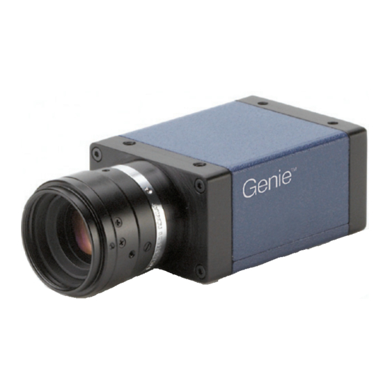
Dalsa Genie M640 User Manual (327 pages)
1 Gb GigE Vision - Monochrome & Color Area Scan
Brand:
Dalsa
| Category:
Digital Camera
| Size: 14.76 MB
Table of Contents
Table of Contents
3
Genie Nano Series Overview
11
Gige with Turbodrive
11
Genie Nano Overview
12
Camera Firmware
12
Monochrome Cameras
13
Part Numbers
13
Color Cameras
15
Optional Hardware Accessories
18
Optional Cable Accessories
19
Software Requirements
20
Sapera LT Development Software
20
Third Party Gige Vision Development
20
About Gige Vision
20
Genie Nano Specifications
21
Common Specifications
21
Sensor Cosmetic Specifications
23
Dynamic Range & Signal to Noise Ratio Measurement Conditions
23
EMI, Shock and Vibration Certifications
24
Mean Time between Failure (MTBF)
25
Sony Sensor Models
26
Specifications: M700, C700
26
Spectral Response (Models 700)
27
Firmware Files for Models M700, C700
28
Specifications: M810, C810
29
Spectral Response (Models 810)
30
Firmware Files for Models 810
30
Specifications: M1450, C1450
32
Spectral Response (Models 1450)
33
Firmware Files for Models 1450
34
Specifications: M1920, C1920
35
Specifications: M1940, C1940
36
Firmware Files for 1920, 1940
37
Spectral Response (Models 1940/1920)
38
Specifications: M1950
39
Firmware Files for M1950
40
Spectral Response (Model M1950)
40
Specifications: C1950
41
Firmware Files for C1950
42
Spectral Response (Model C1950)
42
Specifications: M2020, C2020
43
Firmware Files for Models 2020
44
Specifications: M2050
45
Firmware Files for Model M2050
46
Specifications: C2050
47
Firmware Files for Model C2050
48
Spectral Responses (Models 2020/2050)
49
Specifications: M2420, C2420
50
Firmware Files for Models 2420
51
Specifications: M2450
52
Firmware Files for Model M2450
53
Specifications: C2450
54
Firmware Files for Model C2450
55
Spectral Responses (Models 2420/2450)
56
Specifications: M2450-Polarized
57
Firmware Files for Model M2450-Polarized
58
About Polarization
58
Spectral Responses - IMX250MZR Polarized
60
Extraction Ratio - IMX250MZR Polarized
60
Specifications: M4060
61
Firmware Files for Model M4060
62
Specifications: C4060
63
Firmware Files for Model C4060
64
Specifications: M4040 / M4040-Polarized
65
Firmware Files for Model M4040
66
Specifications: C4040
67
Firmware Files for Model C4040
68
Spectral Responses (Models 4060/4040)
69
Specifications: M4030, C4030
70
Specifications: M4020, C4020
72
Firmware Files for Model 4030 & 4020
73
Spectral Response (Models 4030/4020)
74
On-Semi Sensor Models
75
Specifications: M640, M640-NIR, C640
75
Specifications: M800, C800
77
Firmware Files for Models 640, 800
78
Specifications: M1240, C1240
79
Firmware Files for Models 1240
80
Specifications: M1280, M1280-NIR, C1280
81
Specifications: M1930, M1930-NIR, C1930
83
Specifications: M2590, M2590-NIR, C2590
85
Firmware Files for Models 1280, 1930, 2590
86
Spectral Response (Python 4.8 ΜM Series)
87
Nanoxl Specifications: M5100, M5100-NIR, C5100, M4090, M4090-NIR, C4090
88
Spectral Response (Python 4.5 ΜM Series)
90
Defective Pixel Specification for Models 5100/4090
91
Firmware Files for Models 5100/4090
92
Specifications: C4900
93
Spectral Response (Model C4900)
94
Supplemental Usage Notes
95
Model C4900 Sensor Cosmetic Specifications
95
Firmware Files for this Model
96
Guide to Using a Rolling Shutter Camera
97
Overview of Electronic Rolling Shutter (ERS) Exposures
98
Overview of Global Reset Release (GRR) Exposures
99
Comparison of Similar On-Semi and Sony Sensors
100
Nano Quick Start
102
Testing Nano Without a Lens
102
Testing Nano with a Lens
102
The Camera Works - Now What
102
Connecting the Genie Nano Camera
103
Gige Network Adapter Overview
103
Optimizing the Network Adapter Used with Nano
103
Optimizing Camera/System Performance
103
PAUSE Frame Support
104
Connect the Genie Nano Camera
104
Connectors
105
LED Indicators
106
Camera Status LED Indicator
106
LED States on Power up
106
Genie Nano IP Configuration Sequence
107
Supported Network Configurations
107
Preventing Operational Faults Due to Esd
108
Using Nano with Sapera Api
109
Network and Computer Overview
109
Procedure
110
Camera Firmware Updates
110
Firmware Via Linux or Third Party Tools
110
Gige Server Verification
111
Gige Server Status
111
Quick Test with Camexpert (Windows)
112
About the Device User ID
113
Operational Reference
114
Using Camexpert with Genie Nano Cameras
114
Camexpert Panes
114
Camexpert View Parameters Option
115
Camera Information Category
116
Camera Information Feature Descriptions
116
Power-Up Configuration Dialog
120
Camera Power-Up Configuration
120
Load / Save Configuration
120
Sensor Control Category
121
Sensor Control Feature Descriptions
122
Offset/Gain Control Details (Sony Sensors)
125
Sony Sensors Gain Stage Diagram
125
Offset/Gain Control Details (On-Semi Python Sensors)
126
On-Semi Python Sensors Gain Stage Diagram
126
Bayer Mosaic Pattern
127
Onsemi Python P1 Sensor Artifacts with Fast Readout Mode
127
Fast Readout Mode Artifacts Correction
128
Exposure Alignment Control Modes
128
Synchronous Exposure Alignment Overview
128
Reset Exposure Alignment Overview
129
Exposure Timing for Sony Models
129
Synchronous Mode - Single Frame Exposure
129
Synchronous Mode - 2 Frame Burst Exposure
129
Synchronous Mode - Exposure Timing Specifications
130
Reset Mode - Single Frame Exposure
131
Reset Mode - 2 Frame Burst Exposure
131
Reset Mode - Exposure Timing Specifications
132
Additional Exposure Features
132
Sensor Exposure Timing: Onsemi Python Models
133
Trigger Characteristics: Start of Exposure
133
Auto-Brightness Control Category
134
Auto-Brightness Feature Descriptions
134
Using Auto-Brightness
136
General Preparation
136
Auto-Brightness with Frame Luminance Averaging
137
Auto-Gain
137
Auto-Brightness by Using Auto-Exposure and Auto-Gain
137
I/O Control Category
138
I/O Control Feature Descriptions
139
I/O Module Block Diagram
143
Trigger Mode Details
143
Trigger Source Types (Trigger Mode=On)
144
Input Line Details
144
Trigger Overlap: Feature Details
145
Output Line Details
152
Output High and Output Low Block Diagram
152
Counter and Timer Control Category
153
Counter and Timer Control Feature Description
153
Counter and Timer Group Block Diagram
157
Example: Counter Start Source = off
158
Example: Counter Start Source = Counterend (Itself)
158
Example: Counterstartsource = EVENT and Signal (Edge Base)
159
Example: Counterstartsource = Line (Edge Base) Example
159
Example: Counting Elapse Time
160
Advanced Processing Control Category
161
Advanced Processing Control Feature Descriptions
161
Lookup Table (LUT) Overview
164
LUT Size Vs. Output Pixel Format
164
Gamma Correction Factor
165
Defective Pixel Replacement (Method 3)
166
Example User Defective Pixel Map XML File
166
Defective Pixel Replacement Algorithm Description
167
Color Processing Control Category
168
Color Processing Control Feature Description
168
Color Processing Functional Overview
169
White Balance Operation
170
Simplified RGB Design Firmware Block Diagram
170
Saturation and Luminance Operation
171
Flat Field Correction Category
172
Flat Field Correction Feature Description
172
Cycling Preset Mode Control Category
174
Cycling Preset Mode Control Feature Description
175
Using Cycling Presets-A Simple Example
179
Multi-Exposure Cycling Example Setup
179
Cycling Reset Timing Details
180
Case 1: Cycling with Internal Synchronous Increment
180
Case 2: Cycling with External Asynchronous Increment
180
Using Cycling Presets with Output Controls
181
Feature Settings for this Example
181
Cycling Mode Constraints with a Changing ROI
182
Specifics Concerning Onsemi Sensor Models
182
Specifics Concerning Sony Sensor Models
182
Image Format Control Category
183
Image Format Control Feature Description
184
Width and Height Features for Partial Scan Control
190
Vertical Cropping (Partial Scan)
190
Maximum Frame Rate Examples (Model M/C 700)
191
Maximum Frame Rate Examples (Model M/C 810)
191
Maximum Frame Rate Examples (Model M/C 1450)
191
Maximum Frame Rate Examples (Models M/C 1920, 1940, 1950)
192
Maximum Frame Rate Examples (Models M2020 & M2050)
192
Maximum Frame Rate Examples (Models M2420 & M2450)
193
Maximum Frame Rate Examples (Models M/C 4040 & 4060)
193
Maximum Frame Rate Examples (Models M/C 4020 & 4030)
194
Maximum Frame Rate Examples (Model M/C 640)
194
Maximum Frame Rate Examples (Model M/C 800)
195
Maximum Frame Rate Examples (Model M/C 1240)
195
Maximum Frame Rate Examples (Model M/C 1280)
196
Maximum Frame Rate Examples (Model M/C 1930)
196
Maximum Frame Rate Examples (Model M/C 2590)
197
Maximum Frame Rate Examples (Nanoxl M4090)
198
Maximum Frame Rate Examples (Nanoxl M5100)
199
Maximum Frame Rate Examples (Model C 4900)
200
Horizontal Cropping (Partial Scan)
201
Using the Multiple ROI Mode
201
Important Usage Details
202
Example: Two Horizontal ROI Areas (2X1)
202
Example: Four ROI Areas (2X2)
203
Example: Actual Sample with Six ROI Areas (3X2)
203
Horizontal and Vertical Flip
205
Image Flip - Full Frame
205
Image Flip - Multi-ROI Mode
206
Binning Function and Limitations
207
Horizontal Binning Constraints
207
Vertical Binning Constraints
207
Internal Test Pattern Generator
208
Metadata Control Category
209
Metadata Control Category Feature Descriptions
209
Important Metadata Notes
212
Metadata Analog Gain Value Conversion with Onsemi Sensors
213
Extracting Metadata Stored in a Sapera Buffer
214
Acquisition and Transfer Control Category
216
Acquisition and Transfer Control Feature Descriptions
217
Acquisition Buffering
220
Understanding the Feature - Transferqueuemode
220
Using Transfer Queue Current Block Count with Camexpert
221
Acquisition Abort" Execution Exception with Model C4900
221
Features that Cannot be Changed During a Transfer
221
Action Control Category
222
Action Control Feature Descriptions
223
Gige Vision Action Command Reference
223
Nano Features Supporting Action Command
223
Event Control Category
224
Event Control Feature Descriptions
225
Basic Exposure Events Overview
230
Events Associated with Triggered Synchronous Exposures
230
Events Associated with Triggered Multiple Frame Synchronous Exposures
231
Overview of Precision Time Protocol Mode (IEEE 1588)
232
PTP Master Clock Identity
232
An Example with Two Nano Cameras
232
IEEE 1588 Reference Resources
233
Examples Using Timestamp Modulo Event for Acquisitions
233
Case Examples Overview
233
Case 1: Simple Repeating Acquisitions as Upcoming Events
233
Case 2: Potential Uncertainness to the Start Time
234
Case 3: Timer Reset before the Actual Start Time
235
Case 4: Timer Reset after the Actual Start Time
236
Case 5: Changing 'Timestampmodulo' During Acquisitions
237
Gige Vision Transport Layer Control Category
238
Gige Vision Transport Layer Feature Descriptions
238
Defaults for Devicepacketresendbuffersize
243
Gige Vision Host Control Category
244
Teledyne DALSA Turbodrive
244
File Access Control Category
244
File Access Control Feature Descriptions
245
Updating Firmware Via File Access in Camexpert
248
Overview of the Deviceuserbuffer Feature
248
Overview of Color Correction Coefficients
248
Open Source Software Licenses
249
Implementing Trigger-To-Image Reliability
250
Overview
250
T2IR with Genie Nano
250
Nano Features for T2Ir Monitoring
250
Sapera Tools for Networking
252
Nano Ip Configuration Mode Details
252
Technical Specifications
253
Mechanical Specifications - C & Cs Mount
253
Mechanical Specifications - Nanoxl
255
Additional Notes on Genie Nano Identification and Mechanical
256
Temperature Management
256
Sensor Alignment Specification
256
Connectors
257
10-Pin I/O Connector Pinout Details (Standard Models)
258
Camera DC Power Characteristics
258
I/O Mating Connector Specifications & Sources
259
Power over Ethernet (Poe) Support
260
Input Signals Electrical Specifications
261
External Input Details
261
External Input DC Characteristics
261
External Input AC Timing Characteristics
262
External Inputs: Using TTL/LVTTL Drivers
262
External Inputs: Using Common Collector NPN Drivers
263
External Inputs: Using Common Emitter NPN Driver
263
External Inputs: Using a Balanced Driver
264
Output Signals Electrical Specifications
264
External Output Details and DC Characteristics
264
External Output AC Timing Characteristics
265
External Outputs: Using External TTL/LVTTL Drivers
266
External Outputs: Using External LED Indicators
266
Using Nano Outputs to Drive Other Nano Inputs
268
Computer Requirements for Nano Cameras
269
Host PC System
269
Recommended Network Adapters
269
Ethernet Switch Requirements
270
IEEE 802.3X Pause Frame Flow Control
270
Ethernet to Fiber-Optic Interface Requirements
270
Ec & Fcc Declarations of Conformity
271
Models M/C1920, M/C1940
271
Models M/C640, M/C800, M/C1280, M/C1930, M/C2590
272
Models M/C2020, M/C2050, M/C2420, M/C2450
273
Models M/C4020, M/C4030, M/C4040, M/C4060
274
Models M/C4090, M/C5100
275
Models M/C700, M/C1450
276
Model M/C1950
277
Model C4900
278
Models M/C810
279
Additional Reference Information
280
Choosing a Lens with the Correct Image Circle
280
Lens Options for Models M/C1920, M/C1940
280
Lens Options for Models M/C2450/2420, M/C2050/2020
281
Lens Options for Models M/C4060/4030, M/C4040/4020
281
Lens Options for Models M/C1450
282
Lens Options for XL Models M/C5100, M/C4090
282
Lens Options for Model C4900
283
Lens Options for Models M/C2590
283
Lens Options for Models M/C1930
284
Lens Options for Models M/C1280, M/C1240
284
Lens Options for Models M/C810
285
Lens Options for Models M/C800
286
Lens Options for Models M/C700
286
Lens Options for Models M/C640
287
Additional Lens Parameters (Application Specific)
288
Optical Considerations
288
Illumination
288
Light Sources
289
IR Cut-Off Filters
289
Nano Models with Built-In IR Cut-Off Filters
289
Guidelines for Choosing IR Cut-Off Filters
290
Necessity for White Balance Calibration with IR Filters
290
Back Focal Variance When Using any Filter
291
Lens Modeling
292
Magnification and Resolution
292
Sensor Handling Instructions
293
Electrostatic Discharge and the Sensor
293
Protecting against Dust, Oil and Scratches
293
Cleaning the Sensor Window
294
Ruggedized Cable Accessories
294
Cable Manufactures Contact Information
294
Cable Assembly G3-AIOC-BLUNT1M
295
Cable Assembly G3-AIOC-BLUNT2M
296
Cable Assembly G3-AIOC-BRKOUT2M
298
Nano Generic Power Supply with no I/O
300
Components Express Right-Angle Cable Assemblies
301
Cable Assembly: Right-Angle I/O Bunt End
301
Cable Assembly: Right-Angle I/O to Euro Block
302
Ruggedized RJ45 Ethernet Cables
303
Cable Assembly: Right-Angle Ethernet
304
Right-Angle Cable-Set (Mounted)
305
Alysium-Tech "Extreme Rating" Hiflex Ethernet Cable
306
Ip67 Enclosure Products
307
IP67 Protection Enclosure Designed for Nano
307
IP67 Protection Enclosure Designed for Nano XL
308
Advertisement
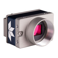
Dalsa Genie M640 User Manual (133 pages)
Genie Monochrome Series
Brand:
Dalsa
| Category:
Digital Camera
| Size: 5 MB
Table of Contents
Table of Contents
3
Genie Monochrome Series Overview
7
Description
7
Genie Application Advantages
8
Product Part Numbers
9
Camera Performance Specifications
10
Certifications
11
Vibration and Shock Certifications
11
Supported Industry Standards
12
Genie Sensor Overview
12
Genie M640-1/2 Specifications
13
Genie M640-1/3 Specifications
14
Genie M1024 Specifications
15
Genie M1280 Specifications
16
Genie M1400-1/2 Specifications
17
Genie M1410-2/3 Specifications
18
Genie M1600 Specifications
19
Application Development Overview
20
Sapera LT Library with Optional Processing
20
Gige Vision Compliant Environment
20
Installing the Genie Camera
21
Warning! (Grounding Instructions)
21
Gige Network Adapter Guideline
21
Supported Network Configurations
21
Installation Overview & Preparations
22
Network and Computer Overview
22
Installation Overview
22
Preventing Operational Faults Due to ESD
23
Sapera Lt Library Installation
23
Genie CD Package Installation
24
Procedure
24
Gige Server Verification
24
Connect the Genie Camera
25
Connectors
25
Status LED Codes
26
Typical LED States on Power up
26
Genie IP Configuration Sequence
27
Gige Server Status
27
Optimizing the Network Adapter Used with Genie
28
Running the Network Configuration Tool
28
Updating Genie Firmware
29
Quick Test with Camexpert
30
About the User-Defined Camera Name
31
Silent Installation of Genie Framework
32
Operational Reference
33
Camera and Sensor Information
33
Access Via Camexpert
33
Power-Up Configuration (Saved User Settings)
34
Power-Up Parameter List
35
Power-Up Control Via Sapera LT or Gige Vision Compliant Applications
35
Camera Information Via Sapera LT or Gige Vision Compliant Applications
36
Sensor Controls
37
Sensor Parameters: Controls Via Camexpert
37
Gain and Black Level Controls
39
Gain and Offset Control Via Sapera LT or Gige Vision Compliant Applications
39
Partial Scan-Window ROI
40
Maximum Frame Rate Examples with Vertical Cropping
40
Frame Rates
41
Window ROI Control Via Sapera LT or Gige Vision Compliant Applications
43
Camexpert Image Buffer and ROI Parameters
44
Binning
45
Binning Control Via Sapera LT or Gige Vision Compliant Applications
46
Trigger Modes
46
Exposure Controls
47
Free-Running Programmable Exposure
47
External Trigger Programmable Exposure
48
External Trigger Level-Controlled Exposure
50
Exposure Controls Via Sapera LT or Gige Vision Compliant Applications
51
Synchronization Timing
52
Synchronous Mode
52
Reset Mode
53
Synchronization Mode Via Sapera LT or Gige Vision Compliant Applications
53
Camexpert I/O Controls Dialog
54
Camexpert I/O Control Dialog
54
General Inputs
55
External Input Signal Opto-Coupler & Debounce Circuit
55
General Inputs: Settings Via Camexpert
55
Input Controls Via Sapera LT or Gige Vision Compliant Applications
56
Strobe and General Outputs
57
General Outputs: Settings Via Camexpert
57
Open and Close Output Settings
58
Strobe on Start of Exposure Event Mode
58
Pulse on Valid Trigger Event Mode
59
Pulse on Invalid Trigger Event Mode
59
Pulse on Start of Readout Event Mode
60
Pulse on End of Readout Event Mode
60
Pulse on End of Acquisition Event Mode
61
Pulse on Input 1 or Input 2 Event Modes
61
Output Control Via Sapera LT or Gige Vision Compliant Applications
62
Genie Processing Features
62
Lookup Table (LUT)
62
LUT Control Via Sapera LT or Gige Vision Compliant Applications
63
Flat Field (Image Shading) Correction
64
Information on the Flat Field Data File
64
Set up Dark and Bright Acquisitions with the Histogram Tool
64
Flat Field Correction Calibration Procedure
66
Using Flat Field Correction
68
Flat Field Correction Control Via Sapera LT or Gige Vision Compliant Applications
68
Image Flip
69
Internal Image Test Patterns
70
Test Image Select Via Sapera LT or Gige Vision Compliant Applications
71
Events
71
Sapera Callbacks
71
Event Selection Via Gige Vision Compliant Applications
72
Using Camexpert to Set Network & Gige Vision Parameters
73
Camexpert Gige Vision Parameters
73
Network Controls Via Sapera LT or Gige Vision Compliant Applications
75
Sapera Supported Features List
76
Accessing Features with Sapera++ LT
76
Feature Type STRING
77
Feature Type ENUM
77
Feature Type INT32
79
Feature Type BOOL
80
Feature Summary List by Function Group
81
Device
81
User Defined Buffers
81
Sensor
81
Sensor Exposure
82
Acquisition ROI
82
Binning Control
82
LUT Control
82
Flat Field Control
82
Trigger Control
83
I/O Control
83
Time Stamp Control
83
Network Parameters
84
User Options
84
Feature Interdependence Diagrams
85
Trigger Enable - TRUE
86
Trigger Enable - FALSE
86
Output Selector
87
Vertical Binning
87
Horizontal Binning
87
Pixel Format
88
Network Configuration Mode
88
Accessing the Genie User Buffer
89
Network Overview & Tools
91
Genie Ip Configuration Mode Details
91
Link-Local Address (LLA)
91
DHCP (Dynamic Host Configuration Protocol)
92
Persistent IP
93
Sapera Camexpert Guide
95
Using Camexpert with Genie Monochrome Cameras
95
Camexpert Panes
96
Camexpert LUT Controls
97
Technical Specifications
99
Mechanical Specifications
99
Genie 3D View with C-Mount and CS-Mount
99
Genie C-Mount and CS-Mount Mechanical Specifications
100
Genie 3D View with Right-Angle C-Mount and CS-Mount
101
Genie Right-Angle C-Mount and CS-Mount Mechanical Specifications
102
Additional Notes on Genie Mechanical
103
Sensor Alignment Specification
103
Connectors
104
12-Pin Hirose Connector Signal Details
104
Genie Signal Electrical Details
105
External Inputs
105
External Outputs
107
RJ45 LAN Ethernet Connector Details
108
Camera Status Led
108
Optical Considerations
109
Illumination
109
Light Sources
109
Filters
109
Lens Modeling
109
Magnification and Resolution
110
Lens Selection Overview
111
Lens Mount
111
Lens Sensor Size
111
Additional Lens Parameters (Application Specific)
112
Sensor Handling Instructions
112
Electrostatic Discharge and the CCD Sensor
112
Protecting against Dust, Oil and Scratches
113
Cleaning the Sensor Window
113
Environment
113
Ruggedized Rj45 Ethernet Cables
114
C/Cs-Mount Nir and Uv Filter
115
Back Focal Variance When Using a Filter
116
Computer Requirements for Genie Cameras
117
Host PC System
117
Ethernet Switch Requirements
117
IEEE 802.3X Pause Frame Flow Control
117
Ethernet to Fiber-Optic Interface Requirements
117
Ec & Fcc Declaration of Conformity
118
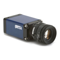
Dalsa Genie M640 User Manual (127 pages)
Genie Monochrome Series GigE Vision Area Scan Camera
Brand:
Dalsa
| Category:
Security Camera
| Size: 2.94 MB
Table of Contents
Table of Contents
3
Genie Monochrome Series Overview
7
Description
7
Genie Application Advantages
8
Product Part Numbers
9
Camera Performance Specifications
10
Electrical Interface
10
Mechanical Interface
10
Optical Interface
10
Certifications
11
Supported Industry Standards
11
Genie Sensor Overview
11
Genie M640-1/2 Specifications
12
Genie M640-1/3 Specifications
13
Genie M1024 Specifications
14
Genie M1400 Specifications
15
Genie M1600 Specifications
16
Application Development Overview
17
Sapera LT Library with Optional Processing
17
Genicam Environment
17
Installing the Genie Camera
19
Warning! (Grounding Instructions)
19
Gige Network Adapter Guideline
19
Supported Network Configurations
19
Using Genie with Ethernet Switches
19
Nstallation
19
Using Genie with a VLAN Ethernet Switch
20
Installation Overview & Preparations
20
Network and Computer Overview
20
Nstallation
20
Installation Overview
21
Sapera Lt Library Installation
21
Genie CD Package Installation
22
Procedure
22
Gige Server Verification
22
Connect the Genie Camera
23
Connectors
23
Status LED Codes
24
Typical LED States on Power up
25
Genie IP Configuration Sequence
25
Gige Server Status
25
Optimizing the Network Adapter Used with Genie
26
Increasing Adapter Buffers and Jumbo Frames
26
Select NIC Advanced Configuration Properties
27
Receive Descriptors
27
Jumbo Frames
28
Running the Network Configuration Tool
28
Updating Genie Firmware
29
Quick Test with Camexpert
31
About the User-Defined Camera Name
32
Operational Reference
33
Camera and Sensor Information
33
Access Via Camexpert
33
Power-Up Configuration
34
Camera Information Via Sapera LT or Genicam Applications
35
Sensor Controls
36
Sensor Parameters: Controls Via Camexpert
36
Parameter Description
37
Gain and Black Level Controls
38
Gain and Offset Control Via Sapera LT or Genicam Applications
38
Partial Scan-Window ROI
39
Window ROI Control Via Sapera LT or Genicam Applications
41
Camexpert Image Buffer and ROI Parameters
42
Binning
43
Binning Control Via Sapera LT or Genicam Applications
44
Trigger Modes
44
Exposure Controls
45
Free-Running Programmable Exposure
45
External Trigger Programmable Exposure
46
External Trigger Level-Controlled Exposure
47
Exposure Controls Via Sapera LT or Genicam Applications
47
Synchronization Timing
48
Synchronous Mode
48
Reset Mode
49
Synchronization Mode Via Sapera LT or Genicam Applications
49
Camexpert I/O Controls Dialog
50
Camexpert I/O Control Dialog
50
General Inputs
51
External Input Signal Opto-Coupler & Debounce Circuit
51
General Inputs: Settings Via Camexpert
51
Input Controls Via Sapera LT or Genicam Applications
52
Strobe and General Outputs
53
General Outputs: Settings Via Camexpert
53
Open and Close Output Settings
54
Strobe on Start of Exposure Event Mode
54
Pulse on Valid Trigger Event Mode
55
Pulse on Invalid Trigger Event Mode
55
Pulse on Start of Readout Event Mode
56
Pulse on End of Readout Event Mode
56
Pulse on End of Acquisition Event Mode
57
Pulse on Input 1 or Input 2 Event Modes
57
Output Control Via Sapera LT or Genicam Applications
58
Genie Processing Features
58
Lookup Table (LUT)
58
LUT Control Via Sapera LT or Genicam Applications
59
Flat Field (Image Shading) Correction
60
Flat Field Correction Calibration Procedure
60
Using Flat Field Correction
62
Flat Field Correction Control Via Sapera LT or Genicam Applications
62
Image Flip
63
Internal Image Test Patterns
64
Test Image Select Via Sapera LT or Genicam Applications
65
Events
65
Sapera Callbacks
65
Event Selection Via Genicam Applications
66
Network Controls & Gige Vision Parameters
67
Camexpert Gige Vision Parameters
67
Network Controls Via Sapera LT or Genicam Applications
68
Genie Power-Up Configuration
69
Power-Up Control Via Sapera LT or Genicam Applications
70
Sapera Supported Features List
70
Accessing Features with Sapera++ LT
70
Feature Type STRING
71
Feature Type ENUM
71
Feature Type INT32
73
Feature Type BOOL
74
Feature Interdependence Diagrams
74
Trigger Enable - TRUE
75
Trigger Enable - FALSE
75
Output Selector
76
Vertical Binning
76
Horizontal Binning
76
Pixel Format
77
Network Configuration Mode
77
Network Tools
79
Ip Configuration Mode Details
79
Link-Local Address (LLA)
79
DHCP (Dynamic Host Configuration Protocol)
80
Persistent IP
80
Network Configuration Tool
81
Quick Genie Network Configuration
81
System Information and Configuration
82
Network Card Information and Configuration
83
Recovering a Camera with an Unknown Persistent IP
84
Sapera Gige Server Details
85
Creating a Status Report
86
Sapera Camexpert Guide
87
Using Camexpert with Genie Monochrome Cameras
87
Camexpert Panes
88
Camexpert LUT Controls
89
Technical Specifications
91
Mechanical Specifications
91
Connectors
92
12-Pin Hirose Connector Signal Details
92
Genie Signal Electrical Details
93
External Inputs
93
External Outputs
94
RJ45 LAN Ethernet Connector Details
94
Camera Status Led
95
Optical Considerations
95
Illumination
95
Light Sources
95
Filters
96
Lens Modeling
96
Magnification and Resolution
96
Sensor Handling Instructions
97
Electrostatic Discharge and the CCD Sensor
97
Protecting against Dust, Oil and Scratches
97
Cleaning the Sensor Window
98
Environment
98
Ruggedized Rj45 Ethernet Cables
99
Computer Requirements for Genie Cameras
100
Host PC System
100
Ethernet Switch Requirements
100
Ethernet to Fiber-Optic Interface Requirements
101
Ec & Fcc Declaration of Conformity
102
Troubleshooting
103
Overview
103
Problem Type Summary
103
Installation Issues and Functional Problems
105
Gige Server Warning Example 1A: IP Error with Multiple Nics
105
Gige Server Warning Example 1B: IP Error with Multiple Nics
106
Gige Server Warning Example 2: Subnet Mask or IP Error
107
Gige Server Warning Example 3: Filter Driver (Corsnid) Disabled
107
Device Available with Operational Issues
108
Firmware Updates
108
Power Failure During a Firmware Update-Now What
109
Streaming Error: no Acquisition with a Timeout Message
109
Disabling Windows Firewall
109
Test a Genie Using Internal Test Patterns
111
Cabling and IP Configuration Issues
111
Streaming Video (Grab) Issues
111
Grab Remains Black
112
Grab Has Random Bad Data or Noise
112
Grab Has Random Bad Data or Noise - Case 1
112
Grab Has Random Bad Data or Noise - Case 2
113
Grab Has Random Bad Data or Noise - Case 3
113
Laptop Computer Networking Issues
113
Configuration Recommendations with Laptops
114
Problems When Changing the Laptop NIC
114
Problems with Disconnecting Nics
115
Ethernet Switch Issues
115
Multiple Camera Issues
115
Camera Exposure Issues
116
Verifying Network Parameters
117
VPN Driver Interference
117
Advertisement
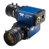
Dalsa Genie M640 User Manual (140 pages)
Brand:
Dalsa
| Category:
Digital Camera
| Size: 6.81 MB
Table of Contents
Table of Contents
4
Genie Monochrome Series Overview
8
Description
8
Genie Application Advantages
9
Product Part Numbers
9
Camera Performance Specifications
11
Certifications
12
Vibration and Shock Certifications
12
Supported Industry Standards
13
Genie M640-1/2 Specifications
14
Sensor
14
Genie M640/M690-1/3 Specifications
15
Genie M1024 Specifications
16
Genie M1280 Specifications
17
Genie M1400-1/2 Specifications
18
Genie M1410-2/3 Specifications
19
Genie M1600 Specifications
20
Application Development Overview
21
Sapera LT Library with Optional Processing
21
Gige Vision Compliant Environment
21
Installing the Genie Camera
22
Arning Rounding Nstructions )
22
Supported Network Configurations
22
Guideline
22
Installation Overview & Preparations
23
Network and Computer Overview
23
Installation Overview
24
Preventing Operational Faults Due to ESD
25
Procedure
26
Nstallation
26
Gige Server Verification
26
Connect the Genie Camera
27
Connectors
27
Status LED Codes
28
Genie IP Configuration Sequence
29
Gige Server Status
29
Optimizing the Network Adapter Used with Genie
30
Running the Network Configuration Tool
30
Updating Genie Firmware
31
Quick Test with Camexpert
33
About the User-Defined Camera Name
34
Ilent Nstallation of Enie Ramework
35
Indows Mbedded Nstallation
36
Operational Reference
37
Camera and Sensor Information
37
Access Via Camexpert
37
Power-Up Configuration (Saved User Settings)
38
Camera Information Via Sapera LT or Gige Vision Compliant Applications
41
Sensor Controls
42
Sensor Parameters: Controls Via Camexpert
42
Gain and Black Level Controls
44
Gain and Offset Control Via Sapera LT or Gige Vision Compliant Applications
44
Partial Scan-Window ROI
45
Window ROI Control Via Sapera LT or Gige Vision Compliant Applications
48
Camexpert Image Buffer and ROI Parameters
49
Binning
50
Binning Control Via Sapera LT or Gige Vision Compliant Applications
51
Trigger Modes
51
Exposure Controls
52
Free-Running Programmable Exposure
52
External Trigger Programmable Exposure
53
External Trigger Level-Controlled Exposure
55
Exposure Controls Via Sapera LT or Gige Vision Compliant Applications
56
Synchronization Timing
57
Synchronous Mode
57
Reset Mode
58
Synchronization Mode Via Sapera LT or Gige Vision Compliant Applications
58
Camexpert I/O Controls Dialog
59
External Input Signal Opto-Coupler & Debounce Circuit
60
Inputs
60
General Inputs: Settings Via Camexpert
61
Input Controls Via Sapera LT or Gige Vision Compliant Applications
62
Strobe and General Outputs
63
General Outputs: Settings Via Camexpert
63
Output Control Via Sapera LT or Gige Vision Compliant Applications
68
Genie Processing Features
68
Lookup Table (LUT)
68
LUT Control Via Sapera LT or Gige Vision Compliant Applications
69
Flat Field (Image Shading) Correction
70
Flat Field Correction Control Via Sapera LT or Gige Vision Compliant Applications
74
Image Flip
75
Internal Image Test Patterns
76
Test Image Select Via Sapera LT or Gige Vision Compliant Applications
77
Sapera Callbacks
77
Event Selection Via Gige Vision Compliant Applications
78
Using Camexpert to Set Network & Gige Vision Parameters
79
Camexpert Gige Vision Parameters
79
Network Controls Via Sapera LT or Gige Vision Compliant Applications
82
Sapera Supported Features List
84
Accessing Features with Sapera++ LT
84
Feature Type STRING
85
Feature Type ENUM
85
Feature Type INT32
87
Feature Type BOOL
88
Feature Summary List by Function Group
90
Feature Interdependence Diagrams
94
Accessing the Genie User Buffer
98
Network Overview & Tools
100
Genie Ip Configuration Mode Details
100
Link-Local Address (LLA)
100
DHCP (Dynamic Host Configuration Protocol)
101
Persistent IP
102
Sapera Camexpert Guide
104
Using Camexpert with Genie Monochrome Cameras
104
Camexpert Panes
105
Camexpert LUT Controls
106
Technical Specifications
108
Mechanical Specifications
108
Genie 3D View with C-Mount and CS-Mount
108
Genie C-Mount and CS-Mount Mechanical Specifications
109
Genie 3D View with Right-Angle C-Mount and CS-Mount
110
Genie Right-Angle C-Mount and CS-Mount Mechanical Specifications
111
Additional Notes on Genie Mechanical
112
Sensor Alignment Specification
112
12-Pin Hirose Connector Signal Details
113
Genie Signal Electrical Details
114
RJ45 LAN Ethernet Connector Details
117
Camera Status Led
117
Optical Considerations
118
Illumination
118
Light Sources
118
Filters
118
Lens Modeling
118
Magnification and Resolution
119
Lens Selection Overview
120
Lens Mount
120
Lens Sensor Size
120
Additional Lens Parameters (Application Specific)
121
Sensor Handling Instructions
122
Electrostatic Discharge and the CCD Sensor
122
Protecting against Dust, Oil and Scratches
122
Cleaning the Sensor Window
123
Environment
123
Rj45 Ethernet Cables
124
C/Cs-Mount Nir and Uv Filter
125
Back Focal Variance When Using a Filter
126
Computer Requirements for Genie Cameras
127
Host PC System
127
Ethernet Switch Requirements
127
Ethernet to Fiber-Optic Interface Requirements
128
Ec & Fcc Declaration of Conformity
129
Advertisement
Related Products
Dalsa M640 NIR
Dalsa M690
Dalsa Genie M640-1/2
Dalsa Genie M640-1/3
Dalsa Genie M690-1/3
Dalsa Genie Monochrome M1280
Dalsa Genie M1400
Dalsa M700
Dalsa M800
Dalsa Genie M1410-2/3
Dalsa Categories
Digital Camera
Security Camera
Media Converter
Security Sensors
IP Camera
More Dalsa Manuals
Login
Sign In
OR
Sign in with Facebook
Sign in with Google
Upload manual
Upload from disk
Upload from URL