Sign In
Upload
Manuals
Brands
Daikin Manuals
Air Conditioner
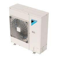
RZQ24TBVJUA
Daikin RZQ24TBVJUA Manuals
Manuals and User Guides for Daikin RZQ24TBVJUA. We have
2
Daikin RZQ24TBVJUA manuals available for free PDF download: Service Manual, Installation Manual
Daikin RZQ24TBVJUA Service Manual (382 pages)
Cooling Only 60 Hz, Heat Pump 60 Hz
Brand:
Daikin
| Category:
Heat Pump
| Size: 23 MB
Table of Contents
Table of Contents
2
Introduction
7
Safety Cautions
8
Caution Items
8
Warnings and Cautions Regarding Safety of Workers
8
Warnings and Cautions Regarding Safety of Users
10
Icons Used
13
Revision History
14
Part 1 General Information
15
Model Names and Power Supply
16
Cooling Only
16
Heat Pump
18
External Appearance
20
Indoor Unit
20
Outdoor Unit
22
Remote Controller
23
Specifications
24
Cooling Only
24
Ceiling Suspended Type
33
Wall Mounted Type
39
Heat Pump
60
Part 2 Refrigerant Circuit
96
Refrigerant Circuit (Piping Diagrams)
97
Outdoor Unit
97
Refrigerant Circuit Part
97
Indoor Unit
103
Functional Parts Layout
105
Rzr18/24Tavju, Rzq18/24Tavju
105
Rzr18/24Tavjua, Rzq18/24Tavjua, Rzr18/24Tbvjua, Rzq18/24Tbvjua
107
Rzr18/24Tavjua, Rzq18/24Tavjua, Rzr18/24Tbvjua
107
Rzq18/24Tbvjua
107
Rzr30-48Tavju, Rzq30-48Tavju
109
Rzr30-48Tavjua, Rzq30-48Tavjua, Rzr30-48Tbvjua, Rzq30-48Tbvjua
111
Rzr30-48Tavjua, Rzq30-48Tavjua, Rzr30-48Tbvjua
111
Rzq30-48Tbvjua
111
Part 3 Remote Controller
113
Applicable Models
114
Names and Functions
115
Brc1E73
115
Brc1H71W
118
Button Locations and Descriptions
118
Overview of Screens
119
Information Screen
124
Simplified Remote Controller
126
Wireless Remote Controller
127
Main/Sub Setting
129
Wired Remote Controller (BRC1E73)
129
Wired Remote Controller (BRC1H71W)
130
When Wireless Remote Controller Is Used Together
132
Address Setting for Wireless Remote Controller
133
Centralized Control Group No. Setting
136
Brc1E73
136
Brc1H71W
138
Wireless Remote Controller
139
Service Settings Menu, Maintenance Menu
140
Brc1E73
140
Service Settings Menu
141
Maintenance Menu
142
Wireless Remote Controller
144
Service Setting
144
Administrator Menu, Installer Menu
145
Brc1H71W
145
Part 4 Functions and Control
146
Operation Mode
147
Basic Control
148
Normal Operation
148
Cooling Operation
148
Heating Operation
148
Compressor PI Control
149
Electronic Expansion Valve PI Control
151
Cooling Operation Fan Control
151
Special Control
152
Startup Control
152
Startup Control in Cooling
152
Startup Control in Heating
153
Oil Return Control
154
Starting Conditions
154
Defrost Control
156
Pump down Residual Control
157
Restart Standby
158
Stop Control
158
Protection Control
159
High Pressure Protection Control
159
Low Pressure Protection Control
160
Discharge Pipe Temperature Protection Control
161
Inverter Protection Control
162
Other Control
164
Demand Operation
164
Heating Operation Prohibition
164
Outline of Control (Indoor Unit)
165
Remote Controller Thermistor
165
Thermostat Control
167
Thermostat Control with Operation Mode Set to AUTO
169
List of Swing Flap Operations
170
Hot Start Control (in Heating Operation Only)
171
Louver Control for Preventing Ceiling Dirt (FCQ Models Only)
172
Drain Pump Control
173
Normal Operation
173
Freeze-Up Prevention
175
Heater Control (Except FTQ-TA Models)
177
Normal Control
177
Overload Control
177
Heater Control (FTQ-TA Models)
178
3-Step Thermostat Processing (FTQ-TA Models)
181
Fan Control (Heater Residual) (FTQ-TA Models)
182
Interlocked with External Equipment (FTQ-TA Models)
182
Field Setting from Remote Controller
185
Wired Remote Controller
185
Simplified Remote Controller
190
Wireless Remote Controller
191
List of Field Settings for Indoor Unit
192
Details of Field Settings for Indoor Unit
196
Remote Controller Thermistor
196
Setting Procedure
201
External ON/OFF Input
203
Factory Setting
203
Auto Restart after Power Failure
204
Airflow Direction Setting
205
Room Temperature Display
208
Operation Control Mode
211
Field Settings from Outdoor Unit
212
Setting Mode and Monitor Mode
212
Setting Mode 1
213
Setting Mode 2
214
Monitor Mode
218
Setting of Low Noise Operation and Demand Operation
220
Image of Operation
220
Setting of Refrigerant Recovery Mode
223
Setting of Vacuuming Mode
223
Check Operation
224
Setting of Auxiliary Heater Control
225
Setting of Heat Pump Lockout and Emergency Heat Mode
226
Test Operation
228
Check Work Prior to Turning Power Supply on
228
Turn Power on
228
Test Operation
229
Error Codes and Corresponding Measures
232
When Turning on Power First Time
234
When Turning on Power the Second Time and Subsequent
234
When an Indoor Unit or Outdoor Unit Has Been Added, or Indoor or Outdoor Unit PCB Has Been Changed
234
Servicing Items to be Confirmed
238
Troubleshooting
238
Precautions for Maintenance
238
Refrigerant Properties (R-410A)
240
Symptom-Based Troubleshooting
241
Indoor Unit Overall
241
With Infrared Presence/Floor Sensor
244
Error Code Via Remote Controller
245
Wired Remote Controller
245
Wireless Remote Controller
246
Error Code Indication by Outdoor Unit PCB
248
Troubleshooting by Error Codes
252
Error Codes and Description
252
Error Codes - Sub Codes
254
Indoor Unit
254
External Protection Device Abnormality (Except FTQ-TA)
255
Troubleshooting
255
External Protection Device Abnormality (FTQ-TA Only)
256
Indoor Unit PCB Abnormality
257
Drain Level Control System (S1L) Abnormality
258
Indoor Fan Motor (M1F) Lock, Overload
260
Indoor Fan Motor Abnormality
262
Applicable Models
262
Blower Motor Not Running
268
Error Reset
268
Indoor Fan Motor Status Abnormality
269
Low Indoor Airflow
270
Swing Flap Motor Abnormality
271
Power Supply Voltage Abnormality
273
Blower Motor Stops for Over/Under Voltage
274
Electronic Expansion Valve Coil Abnormality, Dust Clogging
275
Drain Level above Limit
276
Self-Cleaning Decoration Panel Abnormality
277
Defective Capacity Setting
288
Transmission Abnormality (between Indoor Unit PCB and Fan PCB)
289
Blower Motor Communication Error
291
Thermistor Abnormality
292
Combination Abnormality (between Indoor Unit PCB and Fan PCB)
293
Blower Motor HP Mismatch
294
Indoor Blower Does Not Have Required Parameters to Function
295
Error Code
295
Remote Sensor Abnormality
296
Infrared Presence/Floor Sensor Error
297
Diagnosis Procedure
298
Remote Controller Thermistor Abnormality
302
Outdoor Main PCB Abnormality
303
Activation of High Pressure Switch
304
Activation of Low Pressure Sensor
306
Compressor Motor Lock
308
Outdoor Fan Motor Abnormality
310
Electronic Expansion Valve Coil Abnormality
312
Discharge Pipe Temperature Abnormality
313
Refrigerant Overcharged
314
Thermistor Abnormality
315
High Pressure Sensor Abnormality
316
Low Pressure Sensor Abnormality
317
Inverter PCB Abnormality
318
Radiation Fin Temperature Rise Abnormality
319
Compressor Instantaneous Overcurrent
320
Compressor Overcurrent
321
Compressor Startup Abnormality
322
Transmission Error between Microcomputers on Outdoor Unit Main PCB
323
Inverter Circuit Capacitor High Voltage
324
Radiation Fin Thermistor Abnormality
325
Refrigerant Shortage
326
Power Supply Insufficient or Instantaneous Abnormality
328
Check Operation Not Executed
330
Transmission Error between Indoor Units and Outdoor Units
331
Transmission Error between Remote Controller and Indoor Unit
333
Transmission Error between Main and Sub Remote Controllers
334
Transmission Error between Indoor and Outdoor Units in the same System
335
Improper Combination of Indoor and Outdoor Units, Indoor Units and Remote Controller
336
Incorrect Electric Heater Capacity Setting
338
Address Duplication of Centralized Controller
339
Transmission Error between Centralized Controller and Indoor Unit
340
System Not Set
341
System Abnormality, Refrigerant System Address Undefined
342
Check
343
High Pressure Check
343
Low Pressure Check
344
Superheat Operation Check
346
Power Transistor Check
348
Refrigerant Overcharge Check
349
Refrigerant Shortage Check
350
Vacuuming and Dehydration Procedure
351
List of Inverter-Related Error Codes
352
Concept of Inverter-Related Error Codes
353
Thermistor Check
354
Pressure Sensor Check
357
Broken Wire Check of the Relay Wires
358
Fan Motor Connector Check
359
Electronic Expansion Valve Coil Check
361
Motor Checks
367
Wiring Diagrams
369
Advertisement
Daikin RZQ24TBVJUA Installation Manual (22 pages)
Brand:
Daikin
| Category:
Air Conditioner
| Size: 1 MB
Table of Contents
Table of Contents
5
Safety Considerations
5
Introduction
6
Standard Operation Limit
7
Standard Supplied Accessories
7
Before Installation
7
Selecting Installation Site
7
Precautions on Installation
9
Refrigerant Piping
10
Installation Tools
10
Selecting Piping Material
10
Protection against Contamination When Installing Pipes
10
Pipe Connection
10
Connecting the Refrigerant Piping
10
Thermal Insulation of Piping
11
Air Tight Test and Vacuum Drying
11
Electric Wiring
12
Wiring Connection Example for Whole System
12
How to Lay the Power Supply Wiring and Transmission Wiring
13
How to Connect the Power Supply Wiring
13
Transmission Wiring Connection Procedure
14
Additional Refrigerant Charge
14
Before Adding Refrigerant
14
Checking the Refrigerant Tank
14
Adding Refrigerant
14
Post-Work Checks
15
Test Operation
15
Power On-Check Operation
15
Temperature Control Operation Checklist
16
Final Refrigerant Charge Adjustment
16
Energy Saving and Optimum Operation
16
Three Main Operation Methods Are Available
17
Several Comfort Settings Are Available
17
Setting of Heat Pump Lockout and Emergency Heat Mode
19
Caution for Refrigerant Leaks
21
Advertisement
Related Products
Daikin RZQ24PVJU (9)
Daikin RZQ24PVJU9
Daikin RZQ24MVJU
Daikin SkyAir RZQ24PVJU
Daikin SkyAir RZQ24TAVJU
Daikin RZQ24KCVJK
Daikin RZQ24PVJU8
Daikin SkyAir RZQ24TAVJUA
Daikin RZQ24LCVAK
Daikin RZQ250
Daikin Categories
Air Conditioner
Heat Pump
Chiller
Remote Control
Air Handlers
More Daikin Manuals
Login
Sign In
OR
Sign in with Facebook
Sign in with Google
Upload manual
Upload from disk
Upload from URL