Sign In
Upload
Manuals
Brands
Daikin Manuals
Heat Pump
EWYT032CZO-A1
Daikin EWYT032CZO-A1 Manuals
Manuals and User Guides for Daikin EWYT032CZO-A1. We have
1
Daikin EWYT032CZO-A1 manual available for free PDF download: Installation And Maintenance Manual
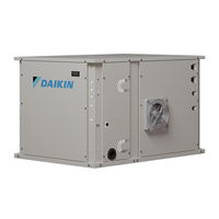
Daikin EWYT032CZO-A1 Installation And Maintenance Manual (59 pages)
Air to water heat pump units with scroll compressors – split version
Brand:
Daikin
| Category:
Heat Pump
| Size: 3.81 MB
Table of Contents
Table of Contents
2
Introduction
5
Precautions against Residual Risks
5
General Description
6
Information about the Refrigerant
7
Safety Devices General Description
7
Table 1 - Physical Properties of R32 Refrigerant
7
Installation Site Requirements for the Indoor Unit
8
Installation Room Area Requirements
8
Table 2 - Space Requirements: NOT Lowest Underground Floor
9
Table 3 - Space Requirements: Lowest Underground Floor
10
Countermeasures
11
Receipt of the Unit
13
Storage
13
Mechanical Installation
14
Safety
14
Handling and Lifting
14
Lifting the Outdoor MONO Unit
14
Figure 1 - Lifting the Outdoor MONO Unit
14
Lifting the Outdoor DUAL Unit
15
Lifting the INDOOR Unit
15
Figure 2 - Lifting the Outdoor DUAL Unit
15
Figure 3 - Indoor Unit Handling & LIFTING
15
Outdoor Unit Positioning and Assembly
16
Figure 4 - MONO Unit Positioning
16
Figure 5 - DUAL Unit Positioning
16
Figure 6 - Mounting Holes Location (Bottom View)
16
Outdoor Unit Minimum Space Requirements
17
Figure 7 - DUAL Unit
17
Indoor Unit Positioning and Assembly
18
Figure 8 - Units Installed Side by Side Along Their Shorter Sides, B or D
18
Figure 9 - Units Installed Side by Side Along Their Longer Sides (Case 1 and Case 2)
18
Additional Installation Site Requirements
19
Figure 10 - Indoor Unit Minimum Space Requirements
19
Combining Units and Options
20
Preparing Refrigerant Piping
20
Figure 11 - Seaside Installation of the Outdoor Unit
20
Figure 12 - Piping Scheme Indoor Unit - Outdoor Unit
21
Table 4 - Temper Grade for Piping Material
21
Table 5 - Pipe Thickness for R32
21
Table 6 - Piping Diameters Table
21
Noise and Sound Protection
22
Water Circuit for Connection with the Unit
22
Figure 13 - Hydraulic Diagram
22
Figure 14 - Hydraulic Elements
22
Table 7 - Piping Length and Height Difference Table
22
Water Piping
23
Flow Switch
23
Repairing and Checking the Water Circuit Connection
23
Water Pressure
23
Water Treatment
23
Table 8 - Water Piping Diameters
23
Table 9 - Flow Switch Setpoint
23
Water Pressure Drops for Filters
24
Indoor Unit Pump
24
Figure 15 - Water Filter Pressure Drops
24
Table 10 - Acceptable Water Quality Limits
24
Operation Limits
25
Figure 16 - External Pressure Head of Water Pump
25
Figure 17 - Operating Limits on EWYT_CZ in Cooling Mode
25
Table 11 - Pump Curves Associated with each Unit Size
25
Operating Stability and Minimum Water Content in the System
26
Figure 18 - Operating Limits on EWYTCZ in Heating Mode
26
Table 12 - Minimum Water Content in the System
26
Water Flow Limits
27
Calibrating the Expansion Vessel
27
Figure 19 - Minimum Water Volume Correction Factor
27
Table 13 - Operating Limits
27
Figure 20 - Initial Expansion Vessel Pressure Based on Maximum Water Volume
28
Electrical Installation
29
General Specifications
29
Electric Connections
29
Cable Requirements
29
Maximum Cable Dimension
30
Safety Device Requirements
30
Phase Unbalance
30
Table 14 - Table 1 of EN602041 Point 5.2
30
Master Wiring Diagram
31
Figure 21 - Master Wiring Diagram
31
Table 15 - Reference No. 1
32
Table 16 - Reference No. 2
32
Table 17 - Reference No. 3
32
Connecting the Refrigerant Piping
33
To Braze the Pipe End
33
Using the Ball Valve
34
Figure 22 - Pipe Brazing
34
Figure 23 - Ball-Valve
34
To Connect the Refrigerant Piping to the Outdoor Unit
35
To Connect the Refrigerant Piping to the Indoor Unit
36
Checking the Refrigerant Piping
37
Pressure Leak Test
37
To Perform Vacuum Drying
37
To Insulate the Refrigerant Piping
38
Charging Refrigerant
38
Precautions When Charging Refrigerant
39
To Determine the Additional Refrigerant Amount
39
Pre-Charging Refrigerant
40
Checks after Charging Refrigerant
41
Operator's Reponsibilities
42
Maintenance
43
Pressure / Temperature Table
44
Routine Maintenance
44
Table 18 - R32 Pressure/Temperature
44
Table 19 - Yearly Maintenance Checklist for the Indoor Unit
44
Table 20 - Standard Routine Maintenance Plan
45
Air Heat Exchanger Maintenance
46
Table 21 - Routine Maintenance Plan for Critical Application And/Or Highly Aggressive Environment
46
Electrical Installation
47
Service and Limited Warranty
47
Refrigerant Circuit Scheme
48
Figure 24 - Refrigerant Circuit (P&ID) Diagram for MONO Circuit EWYT~CZ Unit
48
Figure 25 - Water Circuit P&ID for EWYT-CZ Units
50
Figure 26 - Refrigerant Circuit (P&ID) Diagram for DUAL Circuit EWYT~CZ Outdoor Unit
51
Figure 27 - Refrigerant Circuit (P&ID) Diagram for DUAL Circuit EWYT~CZ Indoor Unit
52
List of the Labels Applied to the Units
53
Table 22 - Labels Applied to the Unit
53
Figure 28 - Labels on the Outdoor Unit
54
Figure 29 - Labels on the Indoor Unit
54
Figure 30 - Labels on the Indoor Unit - Electric Panel Side
55
Commissioning
56
Table 23 - Checks before Starting up the Unit
56
Important Information on the Refrigerant Used
57
Periodic Checks and Commissioning of Pressure Equipment
57
Dismission and Disposal
57
Advertisement
Advertisement
Related Products
Daikin EWYT032CZN-A1
Daikin EWYT032CZP-A1
Daikin EWYT032CZH-A1
Daikin EWYT032CZI-A1
Daikin EWYT016CZN-A1
Daikin EWYT040CZN-A1
Daikin EWYT016CZP-A1
Daikin EWYT090CZP-A2
Daikin EWYT064CZH-A2
Daikin EWYT021CZI-A1
Daikin Categories
Air Conditioner
Heat Pump
Remote Control
Chiller
Fan
More Daikin Manuals
Login
Sign In
OR
Sign in with Facebook
Sign in with Google
Upload manual
Upload from disk
Upload from URL