Sign In
Upload
Manuals
Brands
Daikin Manuals
Furnace
DC92SS
Daikin DC92SS Single-Stage Gas Furnace Manuals
Manuals and User Guides for Daikin DC92SS Single-Stage Gas Furnace. We have
1
Daikin DC92SS Single-Stage Gas Furnace manual available for free PDF download: Installation Instructions Manual
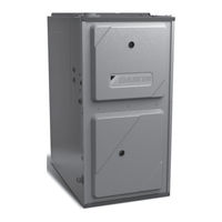
Daikin DC92SS Installation Instructions Manual (48 pages)
Single-Stage Gas Furnace
Brand:
Daikin
| Category:
Furnace
| Size: 4.94 MB
Table of Contents
Table of Contents
1
Safety Considerations
3
Shipping Inspection
4
Electrostatic Discharge (ESD) Precautions
5
To the Installer
5
Product Application
5
Location Requirements & Considerations
6
Clearances and Accessibility
8
Existing Furnace Removal
8
Thermostat Location
9
Combustion & Ventilation Air Requirements
9
Installation Positions
10
Horizontal Applications & Considerations
10
Furnace Suspension
10
Front Cover Pressure Switch Tube Location
10
Drain Trap and Lines
11
Leveling
11
Alternate Electrical and Gas Line Connections
11
Drain Pan
11
Freeze Protection
11
Propane Gas/High Altitude Installations
11
Vent/Flue Pipe & Combustion Air Pipe
11
Dual Certification: Non-Direct/Direct Vent
12
Materials and Joining Methods
12
Proper Vent/Flue and Combustion Air Piping Practices
12
Termination Locations
13
Canadian Vent Pipe & Combustion Air Pipe Requirements
13
Standard Furnace Connections
14
Vent/Flue Pipe
14
Direct Vent Installations
14
Non-Direct Vent Installations
15
Alternate Vent/Flue Location
15
Upflow/Horizontal Models Only
16
Non-Direct Vent (Single Pipe) Piping
17
Vent/Flue Pipe Lengths and Diameters
17
Vent/Flue Pipe Terminations
17
Direct Vent (Dual Pipe) Piping
18
Vent/Flue & Combustion Air Pipe Lengths & Diameters
18
Vent/Flue and Combustion Air Pipe Terminations
19
Vent & Combustion Air Intake Measurements for Standard Horizontal Terminations (Dual Pipe)
19
Vent/Intake Terminations for Installation of Multiple Direct Vent Furnaces
19
Concentric Vent Termination
19
Side Wall Vent Kit
19
Condensate Drain Lines & Drain Trap
19
General Drain Information
19
Field Supplied Drain
20
Upflow Model Installed Vertically
20
Drain Exiting Right Side
20
Drain Exiting Left Side
20
Upflow Model Installed Horizontally with Right Side down
21
Upflow Model Installed Horizontally with Left Side down
21
Upflow Model Installed Horizontally with Left Side down - Alternate
22
Counterflow Model Installed Vertically
22
Drain Exiting Left Side
22
Drain Exiting Right Side
23
Counterflow Model Installed Horizontally with Right Side down
23
Counterflow Model Installed Horizontally with Left Side down
23
Electrical Connections
24
Wiring Harness
24
115 Volt Line Connections
25
Junction Box Relocation
25
24 Volt Thermostat Wiring
25
Single-Stage Heating Thermostat Application
26
Fossil Fuel Applications
26
Gas Supply and Piping
26
High Altitude Derate
26
Propane Gas Conversion
26
Gas Piping Connections
26
Gas Piping Checks
29
Propane Gas Tanks and Piping
29
Circulating Air & Filters
29
Duct Work - Air Flow
29
Checking Duct Static
30
Bottom Return Air Opening [Upflow Models]
30
Filters - Read this Section before Installing the Return Air Duct Work
31
Upright Installations
31
Startup Procedure & Adjustment
31
Furnace Cabinet
31
Drain Trap Priming
31
Furnace Operation
31
Furnace Startup
31
Furnace Shutdown
33
Gas Supply Pressure Measurement
33
Gas Pressure Test
33
Gas Manifold Pressure Measurement and Adjustment
33
Gas Input Rate Measurement (Natural Gas Only)
34
Temperature Rise
34
Circulator Blower Speeds
35
Blower Heat off Delay Timings
35
Normal Sequence of Operation
35
Power up
35
Heating Mode
35
Cooling Mode
36
Fan Only Mode
36
Operational Checks
36
Safety Circuit Description
36
Integrated Control Module
36
Primary Limit
36
Auxiliary Limit
36
Rollout Limit
36
Pressure Switches
36
Flame Sensor
36
Diagnostic Chart
37
Resetting from Lockout
37
Maintenance
37
Annual Inspection
37
Filters
37
Filter Maintenance
37
Filter Removal
37
Horizontal Unit Filter Removal
37
Burners
38
Induced Draft and Circulator Blowers
38
Condensate Trap and Drain System
38
Servicer Only)
38
Flame Sensor (Qualified Servicer Only)
38
Flue Passages (Qualified Servicer Only)
38
Before Leaving an Installation
38
Repair and Replacement Parts
38
Troubleshooting Chart
39
Airflow
41
Wiring Diagram DM92SS* & DC92SS
42
Special Instructions for Products Installed in the State of Massachusetts
43
Start-Up Checklist
44
Advertisement
Advertisement
Related Products
Daikin DC96VE0803BNA
Daikin DC96SE 0403BN
Daikin DC96SE 0603BN
Daikin DC96SE 0804CN
Daikin DC96SN1005CN
Daikin DC96SN1205DN
Daikin DC96VC
Daikin DC96VE0603BNA
Daikin DC96SE Series
Daikin DC96SN0403BN
Daikin Categories
Air Conditioner
Heat Pump
Remote Control
Chiller
Controller
More Daikin Manuals
Login
Sign In
OR
Sign in with Facebook
Sign in with Google
Upload manual
Upload from disk
Upload from URL