Sign In
Upload
Manuals
Brands
Daikin Manuals
Control Systems
D-BACS
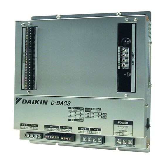
Daikin D-BACS BACnet Interface Controller Manuals
Manuals and User Guides for Daikin D-BACS BACnet Interface Controller. We have
1
Daikin D-BACS BACnet Interface Controller manual available for free PDF download: Design Manual
Daikin D-BACS Design Manual (376 pages)
Buildings Air-conditioning Control System
Brand:
Daikin
| Category:
Control Systems
| Size: 14 MB
Table of Contents
Table of Contents
2
Introduction
9
Advantages of D-BACS over Automatic Control by Central System
9
DAIKIN Building Air-Conditioning Control System (D-BACS) Overview
9
How to Use this Document
11
Safety Precautions
11
Open Network Glossary
12
Part 1 Outline of D-BACS System
18
D-BACS (DAIKIN Building Air Conditioning Control System) System over View
19
D-BACS System Integrated System Diagram
19
System over View
21
Targeted Project Scale and Map
21
Number of Group for Centralized-Control Devices Connectable with Indoor-Units
22
Control Function of the Devices
22
List of D-BACS System Equipment
23
List of Control System Equipment
23
Main Specifications and Functions of the Equipment
25
List of Control System Equipment and Functions
31
Functions of Centralized Controllers
32
Central Control Equipment Combinations
39
List of Applicable Models of DAIKIN
40
Part 2 Fundamental of DIII-NET
42
Design of DIII-NET
43
Features of DIII-NET
43
DIII-NET Design Standard
44
Terminal Number
44
Detail of Outdoor Unit Terminal no
44
Connection Method
45
Wiring Length
51
Unit and Group
52
Number of Connectable Units
53
Flow Chart to Determined the Number of Units to Connected
54
Number of Units to be Connected [VRV] (Supplementary Explanation)
55
Connection of Devices Other than VRV
56
Group and Zone
57
Definition
57
Patterns of Group and Zone
57
Group Address Number
58
Setting Group No. for Centralized Control
59
Zone Address Number
64
Wiring Specifications of DIII-NET
65
Combination of Multiple Central Remote Controllers <DCS302CA61 • DCS301BA61 • DST301BA61
66
Check for Centralized Control Devices in Simultaneous Use
66
Combination of Intelligent Touch Controller and Central Remote Controller
68
Combination of DCS302CA61·DCS301BA61·DST301BA61
69
Sequential Start
71
Under Central Control
71
Error Code on Intial Setting and Wiring Troubles
71
Part 3 Remote Controllers
72
List of Indoor Units with Corresponding Individual Operation Remote Controllers
73
Dimensions of Remote Controllers
75
Wired Remote Controller
75
Wireless Remote Controller / Receiver
76
Simplified Remote Controller
79
Remote Controller for Hotel Use
79
Wired Remote Controller with Weekly Schedule Timer
80
Wired Remote Controller for HRV
80
Functions of Remote Controllers
81
Function List
81
Example of Control by Remote Controller
81
Remote Controller <BRC1C62
82
Simplified Remote Controller <BRC2C51 (BRC2A51)
85
Remote Controller for Hotel Use <BRC3A61
86
Wired Remote Controller with Weekly Schedule Timer <BRC1D61
87
Wireless Remote Controller <BRC4C, 7C, 7E
89
Wired Remote Controller for HRV <BRC301B61
92
Various Control by Remote Controller Control
93
Group Control
93
Forced off or ON/OFF Control
93
Remote Controllers
94
Remote Controller Thermostat
95
KRCS01-1A> Remote Sensor
97
Field Setting by Remote Controller
99
Wired Remote Controller <BRC1C62
99
Wireless Remote Controller <BRC4C, 7C, 7E
102
Simplified Remote Controller <BRC2C51 (BRC2A51)
103
Hrv <Brc301B61
105
Part 4 Intelligent Touch Controller
108
Part Names and Functions
109
Front and Side View
109
Part Names on the Monitoring Screen and the Functions
110
System Configuration
116
System Outline
116
Double Intelligent Touch Controllers
116
Specification
117
Dimension
117
Functions
118
Electric Wiring
121
Terminals on the Back of Intelligent Touch Controller
121
Points of Installation
122
Wiring for Force Stop Input and for Electric Power Distribution
123
Connection to Public Telephone Line
124
Connection to LAN
124
DIII-NET Plus Adaptor Connection
125
Connection for Unification Adaptor
125
DII-NET Plus Adaptor
126
DIII-NET Plus Adaptor
126
Wiring Example for Intelligent Touch Controller (DCS601C51)
128
Web Function
134
Part 5 Control Devices
140
DCS302CA61> Central Remote Controller
141
Function
141
System Configuration
142
Specifications / Dimensions
145
Names and Functions of Operating Part
146
Description of Functions
148
Zone Setting
152
Selection of Control Mode no
156
Initial Setting
159
Electric Wiring
160
Special Function Settings
161
Refreshed Operation
162
Error Diagnosing Function
163
Installation
166
DCS301BA61> Unified ON/OFF Controller
167
Function
167
System Configuration
167
Specification and Dimension
168
Part Names and Functions
168
Initial Setting
170
Electric Wiring
172
Confirming Operation
172
Installation
173
DST301BA61> Schedule Timer
174
Function
174
System Configuration
174
Specification and Dimension
175
Part Names and Functions (DST301BA61)
176
Initial Setting
178
Electric Wiring
179
Installation
180
Error Diagnosing Function
180
Part 6 Intelligent Manager
182
Intelligent Manager Overview
183
Features
183
System Overview
192
Specification
193
Functions
194
System Design of Intelligent Manager
195
System Configuration of Intelligent Manager
195
List of Required Devices for Intelligent Manager System
195
Creation of DIII-NET Wiring Diagram
196
Allocation of Centralized Address
198
Points to Note for Design
199
Use with Other Centralized Devices
200
Installation and Electric Wiring
201
Components
201
Part Name and Function
201
Installation
203
DIII-NET Master" Setting
204
System Wiring
205
Electric Wiring Connection
206
Setting Group No. for Centralized Control
209
Wiring Example
210
Part 7 Interface for Use in Bacnet
216
Bacnet ® Interface
217
Bacnet ® Interfacd
217
Outline and Features
217
System Outline
217
System Configuration
218
Components
219
Dimensions
219
Specifications
219
Bacnet Object List
221
Names and Functions of each Part
222
Electric Wiring
224
Functions
229
Backup Systems for Troubles
231
Adopting "Super Wiring System
233
BMS (Building Management System)
233
Daikin's Interface for Use in Bacnet ® Agreement
234
Wiring Example
236
(Dms502B51)
236
Interface for Use in Bacnet (DMS502B51)
236
Interface for Use in Bacnet
236
Interface for Use in Bacnet ® (DMS502B51)+ Optional Dlll Board (DAM411B51)
237
(Dms502B51)+Optional Dlll Board (DAM411B51)
237
Interface for Use in Bacnet® (DMS502B51) with P.P.D. Application Using Optional DI Board (DAM412 B51)
238
Part 8 Interface for Use in LONWORKS
240
Introduction
242
System Configuration
243
Part Names and Functions
244
Function
245
Overview of Functions
245
Applicable Models
246
Specifications of Devices
247
Hardware
248
Physical Appearance and Branch Connection
248
Definition of LED and Switch
248
Object Details
249
Node Objects
249
DIII-NET Common Objects
249
Air Conditioner Objects
250
Precautions Regarding XIF Files
251
File Name
251
Limitations with Version 3
251
Unused Network Variables
251
Notes for When Commissioning
252
Suspension of Message Transmission When Receiving Set Node Mode Online
252
Reference Materials (Error Code Conversion Table)
253
Electric Wiring
254
Electric Wiring Connection
254
Wiring Example
255
Control-Related Design Keypoints
256
Introduction
256
System Configuration
256
Hardware
258
Outline of Functions
259
LON Communication Specifications
264
Monitoring and Control Restrictions
266
Workflow
268
Check Sheet for Control and Monitoring Items
269
Part 9 Power Proportional Distribution (P
272
Design Guide
273
System Architecture
273
Design Precautions
274
Connection Other than VRV
277
Conditions and Method to Exclude Calculation for Specified Indoor Unit
278
Explanations of Power Proportional Distribution
279
Notes
284
Intelligent Touch Controller (DCS601C51) with the Software for P.P.D. Application (DCS002C51) Including PCMCIA
286
Intelligent Touch Controller (DCS601C51)
287
Intelligent Touch Controller (DCS601C51) with the Software for P.P.D. Application (DCS002C51) Including PCMCIA Card and with the Software for WEB Usage (DCS004A51)
287
WEB Usage (DCS004A51)
287
Intelligent Manager III (DAM602B51) with P.P.D. Application
288
Interface for Use in Bacnet
289
Application Using Optional DI Board (DAM412 B51)
289
Part 10 Adaptor
290
Adaptor for System
291
DCS302A52> Unification Adaptor for Computerized Control
291
Krp2A61 / Krp2A62 / Krp2A53
294
Wiring Adaptor for Electrical Appendices (1)
294
DTA104A61 / DTA104A62 / DTA104A53> External Control Adaptor for Outdoor Unit (Must be Installed on Indoor Units)
304
DTA109A51> DIII-NET Expander Adaptor
312
Dio Unit (DEC102A51)
316
DI Unit (DEC101A51)
328
Ai Unit (DAM101A51)
337
Adaptor for Indoor Unit and Other Equipment
342
KRP4A51 / KRP4A52 / KRP4A53 / KRP4A54> Wiring Adaptor for Electrical Appendices (2)
342
DTA102A52> Interface Adaptor for Skyair Series
351
DTA112BA51> Interface Adaptor for DIII-NET (SA)
354
DTA107A55> Central Control Adaptor Kit
355
DTA103A51> Wiring Adaptor for Other Air Conditioners
361
KRP928B2S> Interface Adaptor for DIII-NET (RA)
365
KRP1B61 / KRP1B56, 59 / KRP1C3> Adaptor for Wiring
369
Advertisement
Advertisement
Related Products
Daikin DBG0723V
Daikin DBG0363B
Daikin DBG0603B
Daikin DBG1203S
Daikin DBH Series
Daikin DBC090 V Series
Daikin DBC102 S Series
Daikin DBC120 V Series
Daikin DBC3004S
Daikin DBH0364B Series
Daikin Categories
Air Conditioner
Heat Pump
Chiller
Remote Control
Air Handlers
More Daikin Manuals
Login
Sign In
OR
Sign in with Facebook
Sign in with Google
Upload manual
Upload from disk
Upload from URL