Sign In
Upload
Manuals
Brands
DÖRR Manuals
Electronic Cigarettes
EcoBell2 SL EC
DÖRR EcoBell2 SL EC Manuals
Manuals and User Guides for DÖRR EcoBell2 SL EC. We have
1
DÖRR EcoBell2 SL EC manual available for free PDF download: Operating Manual
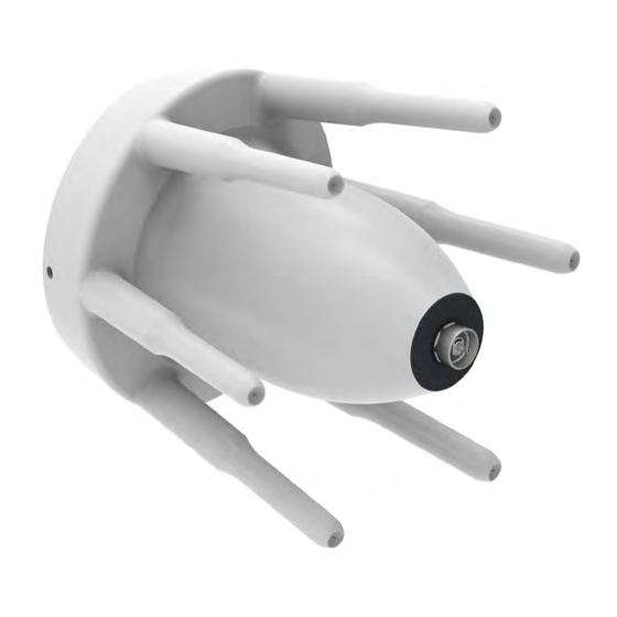
DÖRR EcoBell2 SL EC Operating Manual (156 pages)
Rotating Atomizer with External Charging
Brand:
DÖRR
| Category:
Electronic Cigarettes
| Size: 3 MB
Table of Contents
Section 1
3
Table of Contents
3
1 Introduction
9
Information about the Document
9
Symbols in the Document
9
Intended Use
10
Avoiding Foreseeable Misuses
12
Material Numbers
12
Device Combination
12
Dürr Components Needed for the Use of the Atomizer as 2G Device
12
Dürr Components Needed for the Use of the Atomizer as 3G Device
12
Available Device Combinations
13
Ecobell2 SL EC with "Ecoauc" Control System
13
Total System Ecorp 10 R1100
13
2 Safety
13
Danger Zones
14
Safety Requirements
16
ATEX Marking
16
Residual Risks
18
Parameters
18
Operation
18
Maintenance and Repair
18
Conduct in the Event of a Hazardous Situation
19
Responsibility of the Operator
19
Personnel Requirements
21
Cleaning Staff
21
Assembly Personnel
21
Electrical Personnel
22
Paint Personnel
22
Personal Protective Equipment
22
Danger of Damage to Property
25
Environmental Protection
25
Emergency Shutdown
25
3 Transport and Storage
26
Delivery
26
Storage
26
Storage of Electrode Rings and Atomizer Body
26
4 Operating Principle
27
Brief Description
27
Overview
27
Functionality
28
Assemblies
30
Bell Disk
30
Turbine
32
Shaft Detent
33
Shaping Air
34
Rotational Speedcontrol
35
Valve Block
35
Main Valve Needle
36
Valve for Quick Rinsing the Bell Disk
36
Recirculation for 1K Paints
37
Color Tube
37
Atomizer Body and Sleeve
38
The Shaping Air
38
External Charging
39
Function
39
Clamping Device (Jig)
40
Connections
41
Interfaces
41
Flange Assembly
42
Cable for Potential Equalization
42
High Voltage Line
43
Accessories and Related Parts
43
Accessories
43
Case for Checking High Voltage Shutdown
45
Atomizer Attachment 60 ° (Elbow)
45
Atomizer Pickup
45
Clamp for Atomizer Mount
45
Manual Grounding Rod
45
Assembly Bracket for Atomizer
45
Thread Cleaner
45
Assembly Aid for the Atomizer Body
46
Tool for Disassembly of the Atomizer Body
46
4.6.1.10 External Mixer
46
4.6.1.11 Cable for Potential Equalization
46
4.6.1.12 Tool Set
46
Related Parts
46
High Tension Supply
46
R/O Converter
47
Tools
47
Tool Kit
47
Functionality of Tools
51
Use of Tools in Ex Zones
51
Area of Applicability
52
Restricted Use of Tools in Ex Zones
52
5 Installation and Assembly
54
Installation Illustration
54
Assembly
54
Requirements for the Installation Point
55
Prerequisites for Installation
55
Flange Assembly
55
Assemble the Atomizer
55
Cable and Hose Routing
57
Fasten Electrode Ring
59
Attach the Atomizer to the Flange Package
63
Attaching the Bell Disk
64
Attach Type Plate
65
Final Checks
65
Atomizer
65
Pneumatic Supply
66
Media Lines
66
6 Operation
67
Safety Notes for Operation
67
Danger Due to Explosive Atmosphere
67
Danger Due to High Voltage
67
Material May Leak Uncontrollably at High Speed
67
Danger Due to Harmful or Irritant Materials
68
Danger Due to Rotating Bell Disk
68
General Notes on Operation
68
Valves
69
Noises
69
Vibrations
69
Cleanliness
69
Hoses
69
Grounding and High Voltage
69
Spray Pattern
70
Operating Parameters
70
Painting Data
71
High Voltage
72
Compressed Air
73
Starting Operations
73
Commissioning Notes
73
Commissioning
75
Testing the Paint Flow Control (Volumetric Measurement)
75
Purging
78
Purging Sequence
78
Detergent
78
Checks During Operation
79
7 Cleaning and Maintenance
80
Safety Instructions
80
Cleaning
81
Servicing and Maintenance
82
Cleaning Agents
83
Recommended Cleaning Agents
84
Cleaning and Maintenance Plan
85
Cleaning
87
Cleaning Procedure a
88
Pre-Cleaning with Non-Flammable Detergent
88
Main Cleaning with N-Propanol or Iso-Propanol
88
Drying the Atomizer
88
Cleaning Procedure B
88
Cleaning with Non-Flammable Detergent
88
Scope of Cleaning
89
Atomizer Body
90
Shaping Air Ring
90
Electrode Fingers
91
Bell Disk
92
Drying the Atomizer
93
Final Work
93
Maintenance Work
94
Assembling the Bell Disk
95
Unscrewing the Bell Disk from the Shaft
95
Checking the Distributor Disk
96
Screwing the Bell Disk Onto the Shaft
99
Final Check
102
Installing and Dismantling the Nozzle
102
Dismantling the Nozzle
102
Installing the Nozzle
103
Replacing the Electrodes
103
Removing the Electrodes
104
Installing the Electrodes
104
Dismounting and Mounting Atomizer Body
104
Dismantling the Atomizer Body
104
Install Atomizer Housing
106
Cleaning the Shaping Air Ring
108
Replacing the Contact Ring
109
Dismantling the Contact Ring
109
Installing the Contact Ring
109
Final Work after Maintenance Activity
110
8 Faults
111
Safety Provisions
111
Fault Indicator
112
Behavior During Faults
113
Troubleshooting
113
Mounting the Valve Block
117
Dismantling the Valve Block
117
Mounting the Valve Block
118
Mounting the Turbine
119
Dismantling the Turbine
119
Installation of the Turbine
120
Checking the Position of the Nozzle
121
Installation of the Light Conductor
122
Removing the Light Conductor
122
Cleaning the Light Conductor
124
Testing the Light Conductor
124
Installing the Light Conductor
124
Mounting of the Shaft Detent
124
Dismantling of the Shaft Detent
125
Installation of the Shaft Detent
125
Installing the Main Needle Valve
126
Removing the Main Needle Valve
126
Installing the Main Needle Valve
127
Working on Paint Pipe
128
Removing Paint Pipe
128
Checks on Removed Paint Pipe
128
Disassembling the Paint Pipe
128
Assembling the Paint Pipe
129
Paint Tube with Recirculation
129
Paint Tube with Recirculation
130
Mounting the Paint Pipe
134
Assemble Valve
135
Removing the Valve
135
Assembling Valve
136
Replacing the Hose at the Flange Assembly
137
Resistance Test
138
Final Work after Fault Removal
138
10 Dismantling and Disposal
139
Switching off the Atomizer
139
Separating the Atomizer from the Flange Package
140
Dismantling of the Atomizer
140
Disposal of the Atomizer
141
11 Technical Data
142
Replacement Parts
144
Ordering
144
Replacement Parts List
144
O-Ring 110X2
145
Ring 98X2
145
Compression Spring
145
Piston D8
145
Ring 6X1
145
Lid M12X1
145
Flat Seal 12X1
146
Needle Seat
146
O-Ring 8X1
146
Valve Unit L142 Main Needle
146
Valve Unit L35
146
Ring with Carbon Fiber Brush
146
Gland M27X1.5
146
O-Ring 43X2
147
O-Ring 34X1.1
147
O-Ring 23.47X2.62
147
Complete Electrode
147
O-Ring 7X1.5
148
Sealing Ring D9
148
O-Ring 4X1.5
148
Lid
149
Ring 10X1
149
Pressure Pin
149
Compression Spring
149
29 3/2-Directional Control Valve
149
Plug-In Connection
149
Sealing Ring D8
149
Mixing Tube
149
Sealing Ring D11
149
Section 2
151
12 Contacts and Hotline
152
13 Appendix
152
Check List for Commissioning - External Charging G500
152
Advertisement
Advertisement
Related Products
DÖRR EcoGun AS AUTO
DÖRR EcoGun AL AUTO
DÖRR EcoGun AS MAN EC
DÖRR EcoGun AS AUTO Mini RS
DÖRR EcoPUC MC
DÖRR EcoGun AS AUTO pro HD
DÖRR EcoFlow LPF P
DÖRR EcoPUC A
DÖRR EcoGun AS AUTO Mini FS
DÖRR EcoPump HP
DÖRR Categories
Lighting Equipment
Paint Sprayer
Camera Accessories
Flashlight
Security Camera
More DÖRR Manuals
Login
Sign In
OR
Sign in with Facebook
Sign in with Google
Upload manual
Upload from disk
Upload from URL