Sign In
Upload
Manuals
Brands
Curtis Manuals
Controller
1297
User Manuals: Curtis 1297 Dual Motor Controller
Manuals and User Guides for Curtis 1297 Dual Motor Controller. We have
1
Curtis 1297 Dual Motor Controller manual available for free PDF download: Manual
Curtis 1297 Manual (118 pages)
INTEGRATED TRACTION & HYDRAULIC SYSTEM CONTROLLER
Brand:
Curtis
| Category:
Controller
| Size: 0 MB
Table of Contents
Table of Contents
3
Overview
9
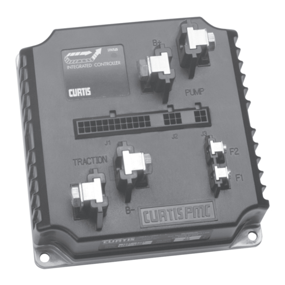
Fig. 1 Curtis PMC 1297 Integrated Traction and Hydraulic System Controller
9
Installation and Wiring
12
Mounting the Controller
12
Fig. 2 Mounting Dimensions, Curtis PMC 1297Controller
12
Connections: Low Current
14
Connections: High Current
15
Wiring: Standard Configuration, Without Multiplexer
16
FIG . 3: Standard Wiring Configuration
16
FIG . 4: Standard Wiring Configuration
16
Wiring: Standard Configuration, with Multiplexer
18
Wiring: Throttles
20
Table 1 THROTTLE WIPER INPUT THRESHOLD VALUES
20
5Kω-0 Two-Wire Resistive Throttle ("Type 1")
21
And Electronic Throttles ("Type 2")
21
0-5Kω Two-Wire Resistive Throttle ("Type 3")
25
Throttles ("Type 4")
25
Wiring: Auxiliary Driver
26
Wiring: Coast and Pick
26
Wiring: Emergency Reverse
26
Wiring: Emergency Reverse Check
26
Wiring: Spyglass Display
27
FIG . 11: Wiring Guide and Mounting Dimensions
27
Curtis Spyglass Display
27
Contactor, Switches, and Other Hardware
28
A Traction Parameters
30
Traction Parameters
32
Acceleration Parameters
32
Drive Current Limit, M1-M2
32
Acceleration Rate, M1-M2
32
Current Ratio
33
Boost Enable
33
Braking Parameters
33
Braking Current Limit, M1-M2
33
Braking Rate, M1-M2
34
Deceleration Rate, M1-M2
34
Coast Deceleration Rate
34
Taper Rate
34
Throttle Deceleration Rate
34
Interlock Braking Current Limit
35
Interlock Braking Rate
35
Interlock Braking Delay
35
Restraint
35
Variable Braking
36
Electromagnetic Brake Type
37
Electromagnetic Brake Delay
37
TABLE 2: Configuration Options: Electromagnetic Brake Driver
38
Speed Parameters
39
Maximum Speed, M1-M2
39
Creep Speed
39
High Speed Latch
39
Interlock Override
39
Load Compensation
40
Throttle Parameters
41
Throttle Type
41
TABLE 3: Programmable Throttle Types: Traction Throttle
41
Throttle Deadband
42
PROGRAMMABLE PARAMETERS (A: Traction / B: Hydraulic / C: Shared)
30
FIG . 13: Effect of Adjusting the Throttle Deadband Parameter
42
Throttle Maximum
44
FIG . 14: Effect of Adjusting the Throttle Max Parameter
44
Throttle Map
46
FIG . 15: Throttle Maps for Controller
46
Pot Low Check
48
FIG . 18: Influence of Various Parameters on Controller
48
Field Parameters
49
Field Minimum
49
Field Maximum
49
Field Map Start
49
Field Map
49
Field Check
50
Emergency Reverse Parameters
51
Emergency Reverse Current Limit
51
Emergency Reverse Check
51
Emergency Reverse Acceleration Rate
51
Emergency Reverse Time Limit
51
Emergency Reverse Direction Interlock
51
Other Traction Parameters
52
Anti-Tiedown
52
Hpd
52
Sro
53
Hydraulic Parameters
54
Pump Parameters
54
Pump Current Limit
54
Maximum Pump Speed
54
No Load Pump Current Limit
54
No Load Maximum Pump Speed
54
Pump Acceleration Rate
55
Pump Deceleration Rate
55
Fig. 20 Hydraulic System Diagram
55
Lift Lockout Parameters
56
Pump Lockout Current Limit
56
Pump Lockout Delay
56
Pump BDI Lockout
56
Pump BDI Lockout Warning
56
Hydraulic Inhibit
56
Valve Control Parameters
57
Lowering Valve Maximum Current
57
Lowering Valve Minimum Current
57
Lowering Valve Dither
57
Lowering Valve Current Acceleration Rate
57
Lowering Valve Current Deceleration Rate
58
Load Hold Delay
58
Lowering Valve Check
58
Hydraulic Throttle Parameters
59
Hydraulic Throttle Type
59
Hydraulic Throttle Deadband
59
Table 4 PROGRAMMABLE THROTTLE TYPES: Hydraulic Throttle
59
Fig. 21 Effect of Adjusting the Hydraulic Throttle Deadband Parameter
60
Hydraulic Throttle Maximum
61
Fig. 22 Effect of Adjusting the Hydraulic Throttle Max Parameter
61
Hydraulic Throttle Map
62
FIG . 23: Hydraulic Throttle Maps for Lift, for Controller
62
Output Response to Throttle Demand
63
FIG . 24: Hydraulic Throttle Maps for Lift, for Controller
63
FIG . 25: Influence of Various Parameters on Controller
63
Variable Lift
64
Variable Lower
64
Shared Parameters
65
Sequencing Delay Parameter
65
Contactor Parameters
65
Main Contactor Interlock
65
Main Contactor Open Delay
65
Main Contactor Diagnostics
65
Multiplexer Enable Parameter
66
Hourmeter Parameters
67
Adjust Hours High
67
Adjust Hours Middle
67
Adjust Hours Low
67
Set Total Hours
68
Set Traction Hours
68
Set Pump Hours
68
Total Service Hours
68
Traction Service Hours
68
Pump Service Hours
68
Total Disable Hours
69
Traction Disable Hours
69
Pump Disable Hours
69
Traction Fault Speed
69
Pump Fault Speed
69
Service Total
70
Service Pump
70
Service Traction
71
Battery Discharge Indicator (BDI) Parameters
71
Reset Voltage
71
Full Voltage
71
Empty Voltage
71
Installation Checkout
72
FIG . 26: Bench Test Setup for Verifying and Adjusting
74
The Controller's Parameters
74
Vehicle Performance Adjustment
75
Traction System Tuning
75
Hydraulic System Tuning
85
Programmer Menus
86
1297 Program Menu
86
1297 Test Menu
90
1297 Diagnostics Menu
91
Diagnostics and Troubleshooting
92
Programmer Diagnostics
92
Table 5 TROUBLESHOOTING CHART
93
LED Diagnostics
95
Table 6 STATUS LED FAULT CODES
95
Spyglass Diagnostics
96
Maintenance
97
Cleaning
97
Diagnostic History
97
APPENDIX A Glossary of Features and Functions
98
FIG . B-1: Mounting Dimensions, Curtis PMC Standard
109
FIG . B-2: Mounting Dimensions, Curtis PMC Potboxes
109
FIG . B-3: Mounting Dimensions, Curtis PMC Footpedal
110
FIG . B-4: Mounting Dimensions, Curtis Throttle WP-45 CP
111
Programmable Parameters
115
Specifications
118
Advertisement
Advertisement
Related Products
Curtis 1298
Curtis 1205
Curtis 1232E
Curtis 1236E
Curtis 1238E
Curtis 1244-46 series
Curtis 1244-56 series
Curtis 1244-65 series
Curtis 1244-66 series
Curtis 1220
Curtis Categories
Coffee Maker
DVD Player
LCD TV
Brewing Systems
MP3 Player
More Curtis Manuals
Login
Sign In
OR
Sign in with Facebook
Sign in with Google
Upload manual
Upload from disk
Upload from URL