Sign In
Upload
Manuals
Brands
Crown Manuals
Amplifier
CE 2000TX
Crown CE 2000TX Manuals
Manuals and User Guides for Crown CE 2000TX. We have
2
Crown CE 2000TX manuals available for free PDF download: Service Manual, Operation Manual
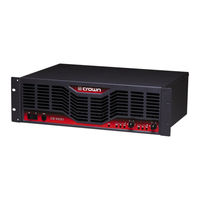
Crown CE 2000TX Service Manual (581 pages)
CE SERIES PROFESSIONAL AUDIO AMPLIFIERS
Brand:
Crown
| Category:
Amplifier
| Size: 16.46 MB
Table of Contents
Service Manual
1
Table of Contents
5
Technical Information
9
The CE-Series
11
CE 2000 Front and Back Panels
11
1 Introduction
11
Warranty
11
Specifications
12
Performance
12
Power
12
Controls
12
Indicators
12
Input/Output
12
Connectors
12
Construction
12
Dimensions
13
Weight
13
2 Maintenance
14
Surface Mount Technology
14
Cautions and Warnings
14
Troubleshooting
14
Pre-AC-Checks
14
Main Module Removal
15
Static Checks
15
Checkout/Adjustment Procedures
15
Equipment Required
16
Initial Conditions
16
Test Procedure
16
Service Kit Wire Extensions
16
CE 1000 with Main Module Removed and Service Kit Installed
17
Bridge MONO
19
3 Circuit Theory
23
Front End Operation
23
Balanced Gain Stage (BGS)
23
Variable Gain Stage (VGS)
23
Error Amp
24
Voltage Amplification
24
Voltage Translator
24
Output Topology
24
Last Voltage Amplifier
24
Bias Servo
24
Pre-Driver
25
Driver
25
Output Devices
25
Flyback Diodes
25
Output Terminating Network
25
Power Supply
25
Low Voltage Supply
25
Bootstrap Supply
25
High Voltage Supply
26
Constant Current Source
26
Protection Circuitry
26
Time Dependent VI Limit
26
Temperature Protection
27
Low-Frequency and Short-Circuit Protection
27
Input Compressor
27
Turn-On Delay
28
Output Relay Muting
28
Input Muting
28
Auxiliary Output Jack
28
Fan Control Circuitry
28
4 Neutrik Connectors
29
Order of Assembly for the Neutrik Speakon NL4FC Connector
29
Stereo Output Wiring
29
Wiring for the Neutrik Speakon NL4FC Connector
29
Detailed Neutrik Speakon NL4FC Connector Assembly
30
Component Documentation
31
General Information
33
Ordering Parts
33
Shipment
33
Standard and Special Parts
33
Terms
33
6 Exploded Views, Parts Lists
35
Assy. CE 1000 Domestic
36
Assy. CE 1000 Domestic
38
Assy. CE 1000 PWA & Chassis
39
HS Assy. CE 1000 Isolated Ch. 1
41
HS Assy. CE 1000 Isolated Ch. 2
43
HS Assy. CE 1000 Isolated Ch.2
46
HS Assy. CE 1000 Non-Isolated Ch. 1
47
HS Assy. CE 1000 Non-Isolated Ch. 2
49
HS Assy. CE 1000 Non-Isolated Ch.2
52
Assy. CE 2000 Domestic
53
Assy. CE 2000 Domestic
55
Assy. CE 2000 PWA & Chassis
56
Assy. CE 2000 PWA & Chassis
57
HS Assy. CE 2000 Isolated Ch. 1
58
HS Assy. CE 2000 Isolated Ch. 2
60
HS Assy. CE 2000 Isolated Ch.2
63
HS Assy. CE 2000 Non-Isolated Ch. 1
64
HS Assy. CE 2000 Non-Isolated Ch. 2
66
HS Assy. CE 2000 Non-Isolated Ch.2
69
Assy, CE 1000A Domestic
70
Assy, CE 2000A Domestic
72
7 Module and Schematic Information
78
Input PWA
78
Main Pwas
78
Schematic Diagrams
78
Module Parts Lists
81
Pwa 102139-6
100
Component Map
100
Parts List
104
Pwa 102139-8
121
Component Map
121
Pwa 102139-9
142
Component Map
142
Component Map
163
Component Map
184
Component Map
205
Component Map
227
Component Map
249
Component Map
271
Component Map
308
Component Map
328
Component Map
350
Component Map
370
Component Map
391
Component Map
412
Component Map
433
Component Map
455
Component Map
477
Component Map
499
Component Map
520
Component Map
542
Field Modifications
545
Timing/Mute Capacitors
545
Bootstrap Resistor Modification
548
Channel 1 Output to Channel 2 Speakon
549
Advertisement
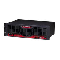
Crown CE 2000TX Operation Manual (28 pages)
Crown Audio Operation Manual Power Amplifier CE2000TX CE Series
Brand:
Crown
| Category:
Amplifier
| Size: 5.81 MB
Table of Contents
Important Safety Instructions
2
Declaration of Conformity
3
Table of Contents
4
1 Welcome
5
Features
5
2 How to Use this Manual
5
3 Setup
6
Unpack Your Amplifier
6
Install Your Amplifier
6
Ensure Proper Cooling
6
Choose Input Wire and Connectors
7
Choose Output Wire and Connectors
8
Wire Your System
9
Stereo Mode
9
Bridge-Mono Mode
10
Input Sensitivity Switch
14
Connect to AC Mains
14
Startup Procedure
14
4 Operation
14
Precautions
14
Controls, Indicators and Connectors
15
5 Advanced Features and Options
16
Protection Systems
16
Bias Servo
16
Fault
16
Ultrasonic and Radio Frequency Protection
16
Drive Protection
16
Compression
16
Power Circuit Breaker
16
Proportional-Speed Fan
16
Advanced Features
16
Advanced Features
17
Fault Monitoring
18
Options
19
Alternate Output Connectors
19
Tamper-Resistant Hole Plugs
19
Optional 0.775V Input Sensitivity Setting
19
6 Principles of Operation
20
7 Troubleshooting
22
8 Specifications
23
9 Service
24
International and Canada Service
24
US Service
24
Service at a US Service Center
24
Factory Service
24
Factory Service Shipping Instructions
24
Packing Instructions
24
Estimate Approval
24
Payment of Non-Warranty Repairs
24
10 Warranty
25
Operation Manual
26
Factory Service Information Form
27
Crown Audio Factory Service Information
27
Advertisement
Related Products
Crown CE 2000
Crown CE-2000A
Crown CE-1000
Crown ce 4000
Crown CE-1000A
Crown CE Series
Crown CH2
Crown Com-Tech CT-400B
Crown Com-Tech CT-400
Crown Com-tech 810
Crown Categories
Amplifier
Microphone
Computer Hardware
Power Tool
Kettle
More Crown Manuals
Login
Sign In
OR
Sign in with Facebook
Sign in with Google
Upload manual
Upload from disk
Upload from URL