Sign In
Upload
Manuals
Brands
CPI Manuals
Amplifier
VZU-6997AC
CPI VZU-6997AC Manuals
Manuals and User Guides for CPI VZU-6997AC. We have
2
CPI VZU-6997AC manuals available for free PDF download: Installation & Operation Manual, Installation, Operation And Preventive Maintenance Manual
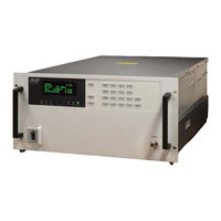
CPI VZU-6997AC Installation & Operation Manual (290 pages)
COMPACT MEDIUM POWER AMPLIFIER
Brand:
CPI
| Category:
Amplifier
| Size: 6.03 MB
Table of Contents
Table of Contents
3
Section S: Safety
12
High-Voltage Equipment Personnel Operating Guidelines
14
When Is Voltage "High
14
General Guidelines
15
Microwave Radiation Personnel Operating Guidelines
19
Discussion
19
General Guidelines
20
Section 1: Introduction
23
About this Manual
24
Major Subsystems and Their Functions
26
Technical Description
27
RF Subsystem
30
Power Supply Subsystem
31
Power Factor Correction Module
31
Power Processor Module
32
High-Voltage Module
32
RF Power Monitor Module
32
Control and Display Modules
33
LRU Philosophy
34
Optional Features
34
Section 2: Unpacking and Installation
36
Pre-Inspection
36
Unpacking
36
Preparing for Installation
37
Installation
37
Mechanical Installation
38
Electrical Connections
38
Prime Power Grounding
39
1/0 Interfaces
40
RF Connections
40
RF Output (Waveguide Connection)
41
Cooling Considerations
42
Section 3: Interfaces
47
CMPA Control Mode Hierarchy
48
Serial Remote Interface
48
RF Switch System Interface
52
Relay Definitions
52
External Interlocks Interface
55
Computer Interface
56
CIF Hardware Configuration
57
Computer Interface (CIF) Protocol
58
Protocol Message Structure
59
Command and Response Format
60
Header and Ending Bytes
61
Command Bytes
62
Response Bytes
62
Reject Bytes
62
Check Bytes
63
Carriage Returns & Line Feeds
64
Commands
65
Slow Commands
70
Status Byte Definitions
70
ID/Version Message
76
Section 4: Initial Power-On and Checkout
78
Pre-Power Procedures
78
Using the Front Panel
80
Initial Power-On Procedures
80
Power-On Self-Test and Heater Time Delay
81
Verifying Operational Settings
82
Setting the Fault and Alarm Trip Points
82
Verifying RF Output Level
86
Verifying RF Alarm and RF Fault Trip Points
88
Testing the CMPA Via Computer Control
89
Testing Optional Equipment
90
Section 5: Operation
93
Essential CMPA Operating Procedures
94
Transmit
94
Normal Shutoff
96
Basic CI\1\Pa Operation
96
CMPA States and Description
96
Initialization and Power-On Self-Test (POST) State
97
Heater Time Delay (HTD) State
98
Standby State
99
Transmit State
100
Fault State
101
CMPA Control Modes and Hierarchy
102
RF Control Modes
103
Special CMPA Functions
105
Factory Authorized Access Mode
105
Terminology
105
Exiting a Menu
106
Data Entry Rules
106
Linearizer Control
107
Quick Access Codes
109
Section 6: Maintenance
112
Scheduled Preventive Maintenance
113
Mechanical Preventive Maintenance
113
Visual Inspection
116
Inspecting & Cleaning Air Filters
117
Checking A3 Leos & Display
117
Collector Air System Maintenance
117
Miscellaneous Cleaning
118
Electrical Preventive Maintenance
118
Spare TWT Maintenance
119
Performance Testing
120
Power and Gain
121
Section 7: Drawings and Schematics
125
Appendix A: Specifications
169
Appendix B: Control Appearance and Content
224
Buttons
224
Leos
226
Beeper
226
Alphanumeric Display Definition
227
Meters
229
Fault Messages that Correspond to Digital Status Lines
230
Fault Messages Generated by Limit Comparisons
231
Alarms
232
General Status Screens
233
Control Menu
234
Data Entry Rules
235
Categories
239
Linearizer Adjustment
242
RF Trip Limits/Switch Port Relay Settings
244
Fault Log
247
Faac
248
Fault Trip Setting
249
Factory Tests
249
Reset Elapsed Time Meter
250
Reset to Factory Defaults
250
CMPA HVPS Test Mode
250
User Tests
251
Time/Date
252
Software Versions
257
Elapsed Hours Information
258
Quick Access Codes
259
POST Faults
261
Software Error Codes
262
Flash RAM- Operating and Programming
262
To Force the CMPA to Use EPROM Contents
263
Reprogramming the Flash RAM
263
Troubleshooting and Error Messages Associated with the Flash RAM
265
Appendix C: Replaceable Parts
274
Appendix D: Warranty/Support Information
274
Return Procedure
274
Advertisement
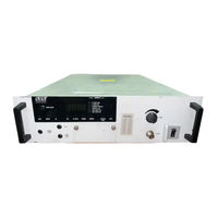
CPI VZU-6997AC Installation, Operation And Preventive Maintenance Manual (140 pages)
CHPA series Compact High Power Amplifier
Brand:
CPI
| Category:
Amplifier
| Size: 0.98 MB
Table of Contents
Table of Contents
3
Safety
13
Introduction
13
High Voltage Equipment
13
Personnel Operating Guidelines
13
When Is Voltage "High
13
General Guidelines
14
Microwave Radiation
16
Personnel Operating Guidelines
16
Microwave Discussion
17
General Microwave Guidelines
17
Physical Safety
18
Lifting Heavy Objects
18
Extending Rack Slides
18
Chapter 1 Introduction
19
Overview
19
Table 1-1. CHPA Model Number and Frequency Ranges
19
Figure 1-1. the CHPA
20
Table 1-1. CHPA Model Number and Frequency Ranges (Continued)
20
About this Manual
21
Major Subsystems and Their Functions
22
Technical Description
22
Rf Subsystem
22
Figure 1-2. CHPA RF Diagram
22
Power Supply Subsystem
24
Figure 1-3. Power Supply Block Diagram
24
Power Factor Correction Module
25
Power Processor Module
25
High-Voltage Module
25
Rf Power Monitor Module
25
Control and Display Modules
26
Lru Philosophy
26
Optional Features
27
Overview
29
Pre-Inspection
29
Unpacking
29
Chapter 2 Unpacking and Installation
29
Preparing for Installation
30
Installation
30
Mechanical Installation
30
Electrical Connections
31
Prime Power
31
Figure 2-1. Rear Panel of CHPA
31
Grounding
32
I/O Interfaces
32
Rf Connections
32
Rf Output (Waveguide Connection)(J3)
33
Cooling Considerations
33
Chapter 3 Interfaces
35
Overview
35
Chpa Control Mode Hierarchy
35
Serial Remote Interface
36
Figure 3-1. Setting Termination Resistors
37
Table 3-1. Serial Remote Interface Pin Assignment (J6)
37
Rf Switch System Interface
38
Relay Definitions
38
Table 3-1. Serial Remote Interface Pin Assignment (J6) (Continued)
38
Table 3-2. Low RF Relay Function
39
External Interlocks Interface
40
Table 3-3. RF Switch Pin Assignment (J5)
40
Figure 3-2. Setting Serial Format
41
Table 3-4. Interlocks Interface Pin Assignments (J8)
41
Computer Interface
42
Cif Hardware Configuration
42
Computer Interface (Cif) Protocol
43
Protocol Message Structure
43
Table 3-5. CIF (Computer Interface) Pin Assignment (J7)
43
Command and Response Format
44
Header and Ending Bytes
44
Address Byte
45
Command Byte
45
Response Byte(S)
45
Reject Byte(S)
45
Table 3-6. Reject Bytes
45
Check Byte
46
Table 3-6. Reject Bytes (Continued)
46
Carriage Returns and Line Feeds
47
Commands
47
Table 3-7. Query Commands
48
Table 3-8. CHPA Commands
49
Slow Commands
50
Table 3-10. Interface Commands
50
Table 3-8. CHPA Commands (Continued)
50
Table 3-9. Slow Commands
50
Status Byte Definitions
51
Table 3-11. Summary Status Bytes
51
Table 3-12. Secondary Status Bytes
52
Table 3-13. Fault and Miscellaneous Status
53
Table 3-13. Fault and Miscellaneous Status (Continued)
54
Table 3-14. Information/Error Messages
54
ID/Version Message
55
Table 3-14. Information/Error Messages (Continued)
55
Chapter 4 Initial Power on and Checkout
57
Overview
57
Pre-Power Procedures
57
Using the Front Panel
58
Figure 4-1. the CHPA Series Front Panel
58
Initial Power-On Procedures
59
Power-On Self-Test and Heater Time Delay
59
Verifying Operational Settings
60
Setting the Fault and Alarm Trip Points
60
Table 4-1. Helix and RF Settings Ranges
61
Setting Serial Remote and Cif Port Parameters
62
Table 4-1. Helix and RF Settings Ranges (Continued)
62
Verifying Rf Output Level
63
Verifying Rf Alarm and Rf Fault Trip Points
64
Testing the Chpa Via Computer Control
65
Testing Optional Equipment
65
Remote Control Interface
65
Chapter 5 Operation
67
Overview
67
Figure 5-1. Control Panel
67
Essential Chpa Operating Procedures
68
Transmit
68
Normal Shutoff
69
Basic Chpa Operation
69
Chpa States and Description
70
Initialization and Power-On Self-Test (Post) State
70
Heater Time Delay (Htd) State
71
Standby State
72
Transmit State
73
Fault State
73
Chpa Control Modes and Hierarchy
74
Rf Control Modes
75
Figure 5-2. Example: Accessing CHPA Features
75
Special Chpa Functions
76
Factory Authorized Access Mode
76
Terminology
76
Exiting a Menu
77
Data Entry Rules
77
Table 5-1. Front Panel Categories
77
Table 5-1. Front Panel Categories (Continued)
78
Quick Access Codes
79
Chapter 6 Maintenance
83
Overview
83
Scheduled Preventive Maintenance
83
Mechanical Preventive Maintenance
84
Table 6-1. Preventive Maintenance Schedule CHPA
84
Table 6-1. Preventive Maintenance Schedule CHPA (Continued)
85
Table 6-2. Recommended Test and Service Equipment Description
85
Visual Inspection
86
Table 6-2. Recommended Test and Service Equipment Description (Continued)
86
Inspecting and Cleaning Air Filters
87
Checking A3 Leds and Display
87
Collector Air System Maintenance
87
Checking B1 Collector Blower
88
Miscellaneous Cleaning
88
Electrical Preventive Maintenance
88
Spare Twt Maintenance and Periodic Operation of the Amplifier
88
Power and Gain
90
Figure 6-1. TWT Amplifier Test Setup
92
Performance Testing
90
Chapter 7 Drawings and Schematics
93
Table 7-1. Compact HPA Drawings
93
Chapter 8 Supplementary Data
95
Appendix A Specifications
97
Appendix B Control Appearance and Content
99
Overview
99
Buttons
99
Figure B-1. Front Panel Picture
99
B.1 Overview
99
Leds
100
Table B-1. Front Panel Button Description
100
B.3 Leds
100
Beeper
101
Alphanumeric Display Definition
101
Table B-2. Front Panel Leds
101
B.4 Beeper
101
Meters
103
Hvps Meter Display List
103
Rf Meters
103
Meter Order
103
B.6 Meters
103
Meter List
104
Fault Messages that Correspond to Digital Status Lines
104
B.6.4 Meter List
104
Fault Messages Generated by Limit Comparisons
105
Alarms
106
B.9 Alarms
106
Control Menu
107
Data Entry Rules
107
B.10 Control Menu
107
Table B-3. Front Panel Categories
108
Table B-3. Front Panel Categories (Continued
109
Table B-4. Default Values for User Features
110
Categories
111
Rf Control
111
Table B-5. RF Display Preferences
111
B.11.1 Categories
111
Linearizer Control (Optional
112
Linearizer Adjustment
113
B.12 Linearizer Adjustment
113
Rf Trip Limits/Switch Port Relay Settings
114
Table B-6. RF Alarms and Faults
114
Fault Log
115
B.13.1 Fault Log
115
Factory Authorized Access Code (Faac
116
Fault Trip Setting
117
Factory Tests
117
Reset Elapsed Time Meters
117
Reset to Factory Defaults
118
Chpa Hvps Test Mode
118
User Tests
119
Table B-7. User Tests and Results
119
B.13.8 User Tests
119
Time/Date Set
120
Table B-8. Time/Date Settings
120
Remote/Computer Interface Parameters
121
Table B-9. Computer Interface Parameters
121
Table B-9. Computer Interface Parameters (Continued
122
Table B-10. Computer Interface Parameters
122
Table B-10. Computer Interface Parameters (Continued
123
Software Versions
124
Elapsed Hours Information
124
Table B-11. Software Versions
124
Table B-12. Elapsed Hours Feature
124
B.13.11 Software Versions
124
Quick Access Codes
125
Post Faults
127
Software Error Codes
127
Table B-13. POST Faults
127
Table B-14. Software Error Codes
127
B.15 Post Faults
127
Flash Ram - Operation and Programming
128
Reprogramming the Flash Ram
128
To Force the Chpa to Use Eprom Contents
128
Troubleshooting and Error Messages Associated with the Flash Ram
130
Appendix C Replaceable Parts
133
Appendix D Warranty and Support Information
135
Appendix E Options and Features
137
Appendix F Optional L-Band Buc
139
Overview
139
F.1 Overview
139
Precautions
140
F.2 Precautions
140
Advertisement
Related Products
CPI VZU-6997AB
CPI VZU-6997AE
CPI VZU-6997AG
CPI VZU-6997AA
CPI VZU-6997AD
CPI VZU-6997AJ
CPI VZU-6997CY
CPI VZU-6997AX
CPI VZU-6997AY
CPI Satcom Division VZU-6997 Series
CPI Categories
Bank Note Validator
Amplifier
Cash Counters & Coin Sorters
Scooter
Antenna
More CPI Manuals
Login
Sign In
OR
Sign in with Facebook
Sign in with Google
Upload manual
Upload from disk
Upload from URL