Sign In
Upload
Manuals
Brands
COUSINS Manuals
Accessories
3300-CTA
COUSINS 3300-CTA Manuals
Manuals and User Guides for COUSINS 3300-CTA. We have
1
COUSINS 3300-CTA manual available for free PDF download: Instruction & Maintenance Manual
COUSINS 3300-CTA Instruction & Maintenance Manual (473 pages)
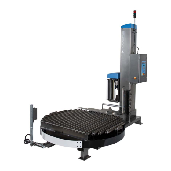
CONVEYORIZED PLATFORM AUTOMATIC STRETCH-WRAPPING SYSTEM & OPTIONS
Brand:
COUSINS
| Category:
Accessories
| Size: 15 MB
Table of Contents
Rapid Checklist
3
Table of Contents
5
1:0 before Starting the Machine
9
2:0 Specific Cautions and Warnings
11
3:0 Machine Description
13
3:1 Machine Specifications
14
Control
14
Motors
14
Power
14
3:2 Conveyor Specifications
15
Capacity
15
Drive Train
15
Rollers
15
4:0 Installation
17
4:1 Moving the Machine
17
4:2 Unpacking and Inspection
17
4:3 Extended Tower Assembly (Optional)
18
4:3:1 Fold-Down Tower Assembly
18
Test for Proper Machine Operation
19
To Remove the Front or Rear Tower Guard
19
4:3:2 Tower Guard Removal / Installation
19
4:4 Installing the Machine
19
4:5 Pre-Operation Check and Final Assembly
20
4:6 General Power Requirements
22
5:0 Set-Up and Operating Procedures
23
5:1 Operating Controls - Control Panel Door
23
5:1:1 Main Disconnect Switch
24
5:1:2 Emergency Stop Push-Pull Button
24
5:1:3 Power on / Reset Push-Button
24
5:1:4 Wrap Cycle Start Push-Button
25
5:1:5 Carriage Raise Speed Control Potentiometer
25
5:1:7 Force to Load Control Potentiometer
25
5:1:8 Eject Load Push-Button (Basic 2-Station System Only)
26
5:1:9 Infeed Conveyor Jog Push-Button (Multi-Station System)
26
5:1:10 Turntable Conveyor Jog Push-Button (Multi-Station System)
27
5:1:12 Control Mode Manual / Auto Push-Button (Optional)
27
5:2 Operator Interface Panel (HMI)
28
5:2:1 Control Power Disabled Screen
28
5:2:2 Start-Up Splash Screen
29
5:2:3 Manual Functions #1 Screen
29
5:2:3:1 Turntable Jog Button
30
5:2:3:2 Film Carriage Raise Button
30
5:2:3:3 Film Carriage Lower Button
30
5:2:4 Manual Functions #2 Screen
30
5:2:4:1 Film Clamp Open / Close Button
31
5:2:4:2 Cut / Wipe Arm Advance Button
31
5:2:4:3 Cut / Wipe Arm Retract Button
31
5:2:5 Conveyor Manual Functions Screen (Optional)
32
5:2:5:1 Conveyor Manual Reverse Button
32
5:2:6 Machine Settings Screens
33
5:2:7 Wrap Count Settings Screen
33
5:2:7:1 Top Wrap Revolutions Preset Display
34
5:2:8 Photo-Eye Settings Screen
35
5:2:8:1 Auto Load Height Photo-Eye Off/On Button
35
5:2:8:2 Top of Load Film Overlap Display
36
5:2:9 Clamp Open Height Screen
37
5:2:9:1 Clamp Open Height Display
37
Clamp Open Height Data Input
38
5:2:10 Film Force Settings Screen
38
5:2:10:1 Reduced Bottom Film Force Button
39
5:2:11 Low Load Settings Screen
39
5:2:11:1 Enable Low Load Wrap Button
40
5:2:12 Conveyor Settings Screen (Optional)
40
5:2:12:1 Infeed Conveyor Auto Start Button (Optional)
41
5:2:12:2 Seconds Infeed Start Delay Display (Optional)
41
5:3 Operating Controls - Inside Control Panel
42
5:3:1 PLC Analog Trim-Pots
42
5:3:1:1 Analog Trim-Pot #V0
42
5:3:1:2 Analog Trim-Pot #V1 - Decel (Delay) Timer
43
5:4 Wireless Remote Control
43
5:4:1 Wireless Remote Start Push-Button
44
5:4:1:1 Basic 2-Stage System
44
5:4:1:2 Multi-Stage System with Optional Powered Infeed Conveyor
44
5:5 Remote Start / Stop Pendant (Optional)
44
5:5:1 Remote Start Push-Button
45
5:5:1:1 Basic 2-Stage System
45
5:5:1:2 Multi-Stage System with Optional Powered Infeed Conveyor
45
5:5:2 Remote Stop Push-Button
45
5:6 Remote Lanyard Start Switch (Optional)
45
5:7 Machine Status Indicator Beacon
46
5:7:1 Machine Ready (Green) Status Indicator Beacon
46
5:8 Super Rapid Thread II™ Prestretch Door Safety Switch
47
5:9 Turntable Speed Adjustment (Optional)
47
5:9:1 Turntable Start Speed Setting
48
5:9:2 Turntable Run (Fast) Speed Setting
48
5:9:3 Turntable Slow Speed Setting
48
5:10 Film Carriage Speed Set-Up
49
5:10:1 Carriage Raise Speed
49
5:10:2 Carriage Lower Speed
49
5:11 Film Carriage Limit Switch Striker Adjustment
49
5:12 Auto Load Height Sensing Photo-Eye Adjustment
50
5:13 Film Carriage Safety Switch
50
6:0 Wrapping a Load
53
6:1 Placing the Load Onto the Turntable Conveyor
53
6:2 Threading the Super Rapid Thread II™ Prestretch
54
Attaching the Film to the Film Threading Hook
55
Threading the Film through the Film Carriage
56
6:3 Attaching the Film to the Film Clamp
57
6:4 Starting the Wrap Cycle (Initial Set-Up)
57
6:5 Wrap Cycle Sequence of Operation
58
6:5:1 Automatic Wrap Cycle Sequence
58
6:5:2 Film Fault Reset Sequence
59
6:6 Re-Wrapping the Load
60
6:7 Removing the Wrapped Load
60
7:0 Remedial Adjustment
63
7:1 Turntable Soft-Start
63
7:2 Load Toppling or Sliding
63
7:3 Film Tearing & Puncturing
63
7:4 Film Roping Roller
65
7:5 Uneven Top Surfaces
65
7:6 Auto Load Height Photo-Eye False Signals
66
7:7 Top Sheet Application
66
7:8 Reinforcing Band Application
67
7:9 Film Clamp
68
Maintenance Requirements
69
Lubrication
69
Maintenance Frequency Recommendations
69
9:0 Maintenance and Adjustments
71
9:1 Film Carriage Lift Chain Adjustment
71
Disconnect Electrical Power from the Machine!
72
9:2 Turntable Removal & Installation
72
9:2:1 Turntable Conveyor Removal
73
9:3 Turntable Drive Chain Adjustment
74
9:4 Turntable Support Wheels
75
9:5 Film Carriage Limit Switch Lever Arm Adjustment
75
9:6 Auto Load Height Sensing Photo-Eye Adjustments
75
9:7 Variable Frequency Drives
76
9:8 Turntable Positive Alignment Set-Up and Adjustment
77
9:9 Turntable Home Position Proximity Sensor Adjustment
78
9:10 Dancer Proximity Sensor Installation & Adjustment
78
9:11 Ni-Chrome Film Cutter Hot-Wire Installation
80
9:12 Film Cut / Wipe Arm Adjustment
82
9:13 Film Carriage Safety Switch Adjustment
84
Descent Obstruction Plate
85
9:14 Prestretch Roller Cleaning Procedure
86
10:0 Trouble-Shooting
87
10:1 Trouble-Shooting Operator Interface Fault Messages
87
10:1:1 Film Fault
88
10:1:2 Film Carriage Safety Switch Tripped Fault
89
10:1:3 Film Cut/Wipe Arm Watchdog Timer Fault
90
10:1:4 Film Carriage Height Sensor Fault
91
10:1:5 Variable Frequency Drive Fault
92
10:1:6 Wrap Cycle Watchdog Timer Fault
93
10:2 Trouble-Shooting Guide
94
11:0 Parts Lists
107
Material List
109
Cautions
149
Mounting
149
Wiring Connections
149
Specifications
149
I/O Circuit Diagrams
150
Bgs/Fgs Function
150
Stability Indicator
150
Timer Function
150
Highlights
151
Connection Diagram
151
Excess Gain Curve
151
Photoelectric Reflex Sensor
151
Electrical Characteristics
153
Setting up Procedure
153
Protections
153
References
153
Inductive Proximity Sensors
155
Mechanical Installation
155
Electrical Installation
155
Installation Precautions
155
Machine Cabling Accessories
156
Dimensions
156
Connection Schemes
156
Characteristics
157
Typical Applications
157
With Neon Lamp
158
With LED
158
Standard Type
158
Product Type
158
Contact Rating
159
Contact Characteristics
159
EN60947-5-1 Performance
159
Protective Construction
159
Adjustable Rod Type
161
Adjustable Roller Arm Type
161
Flexible Rod Type
161
Spring Wire Type
162
Remote Wire Control Type
162
Mounting Dimensions
163
VL Conduit Adapter
163
Spring Type
163
Indicator Lighting Circuit
163
Wiring
164
Applicable Wire
164
Head Direction Change
164
Product Data Sheet
165
Check the Delivery of the Drive
168
Check the Line Voltage Compatibility
168
Mount the Drive Vertically
168
Connect the Drive: Power
169
Control Choice
169
Apply Power to the Drive
169
Set Motor Parameters
169
LOCAL Configuration
170
REMOTE Configuration
170
Set Control Choice
170
Menus Structure
171
Diagnostics and Troubleshooting
172
Drive Does Not Start, no Error Code Displayed
172
Fault Detection Codes that Cannot be Reset Automatically
172
Remote Keypad Error Messages
177
Ordering Example
184
SE Encore Speed Reducers
185
Selection
186
Mounting Positions
186
Shaft Alignment and Loading
186
Mounting Considerations
186
Sealed Vs. Vented Speed Reducer
187
Speed Reducer Assembly
187
C Face Motor Mounting
187
Change in Speed Reducer Operating Temperature
188
Ingestion of Air and Contaminant by a Radial Seal
189
The Effects of Temperature and Pressure on Seal Operating Life
189
Courtesy of Parker Hannifin Corporation
189
Performance Issues with Bladders and Expansion Chambers
190
SE Encore Venting Solution Is a Standard Feature
191
Maintenance
191
Factory Filling and Universal Mounting
191
Ambient Temperature
192
Initial Start-Up
192
Oil Change Instructions
192
Long Term Storage or Infrequent Operation
192
Oil Seals and Wear Components
193
Low Input Speeds
193
Oil Temperature
193
Grease Fittings
193
Warnings and Cautions
196
Lock-Out/Tag-Out
196
Grounding
196
Protective Guarding / Loose Clothing, Etc.
196
Troubleshooting
198
Safety Notes
199
Safety & Information Symbols
199
Safety Warnings
199
Transportation and Handling
199
Disposal
200
Commissioning after Long-Term Storag
201
Long-Term Storage
201
Commissioning
201
Storage & Commissioning
201
Unit Installation
202
Installation Site
202
Mounting Position
202
Reducer Mounting
202
Concrete Foundation
203
Bolt Connections for Footed & Flange Mounted Units
203
Mounting the Prime Mover
203
Vent Locations
204
Harmful Situation
204
Safety Notice
205
General Instructions
205
Brake Operation
205
Installation & Maintenance
205
General Selection Considerations
206
Brake Torque Adjustment
206
Spanner Nut Adjustment
206
Brake Control Rectifiers
207
Rectifier Advantages
207
Rectifier Types
207
Brake Switching Options
207
GVE/GHE Dimensions
208
GUE Dimensions
208
GVE/GHE Braking Methods
208
PMG 500 Push-Hybrid Rectifier
209
Fast & very Fast Stopping (DC-Switching)
209
Standard Stopping (Ac-Switching)
209
General Maintenance
211
Brake Hand-Lever Installation and Adjustment
211
Brake Air Gap
211
Hand Release Lever (HL)
211
Setting the Brake Air Gap
212
Brake Air Gap Settings
212
Brake Rotor (Brake Disc) Wear Assessment
213
Optional Brake Accessories
213
Locking Hand Release Lever (FHL)
213
Required Tools
213
Parts List - Precima Brakes
214
Spare Parts
214
Brake Times & Electrical Selection
215
Recommended Applications
215
Typical Connection Diagrams
217
Typical Connection Diagrams - Single Phase Motors
221
Troubleshooting Information
222
Installation & Operating
223
Order and Product Data
224
Contents
224
Overview
225
Motor Types
225
Enclosure Types
225
Totally Enclosed Fan Cooled (TEFC)
225
Nameplate Data
226
Motor Nameplate Information
226
Motor Options and Nomenclature
227
Motor Nomenclature
227
Ordering Examples
227
Application Conditions
228
Transportation
228
Storage
229
Safety Considerations
229
Five Safety Rules
229
Qualified Personnel
229
Safety Considerations Ctd
230
General Warnings and Cautions
230
Verification
231
Bearing Lubrication
231
Checking the Insulation
231
Electrical Connections
232
Terminal Board and Grounding Screws
232
Terminal Box Cover Screws
232
Wiring Diagrams
233
Frames 63-132
233
Frames 160 +
233
Motor Accessories
235
Blower Cooling Fan (Option F & FC)
235
Thermostats (Option TW and Option 2TW)
236
Space Heaters (Option SH)
236
Thermistors (Option TF)
236
Encoder (Option IG)
236
Inspection
237
Inspection Guidelines
237
Repair
239
Removing and Replacing Integral Motors
239
Testing
240
Removing and Replacing NEMA C-Face
240
IEC Fange-Mounted Motors
240
Static Testing
240
Global Variables
366
Conveyor_Outputs
386
Faults
391
Hmi
403
Main
414
Outputs
422
Advertisement
Advertisement
Related Products
COUSINS Categories
Accessories
More COUSINS Manuals
Login
Sign In
OR
Sign in with Facebook
Sign in with Google
Upload manual
Upload from disk
Upload from URL