Sign In
Upload
Manuals
Brands
Copeland Manuals
Refrigerator
ZXLE025E
Copeland ZXLE025E Manuals
Manuals and User Guides for Copeland ZXLE025E. We have
1
Copeland ZXLE025E manual available for free PDF download: Application Manual
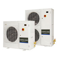
Copeland ZXLE025E Application Manual (66 pages)
Outdoor refrigeration units
Brand:
Copeland
| Category:
Refrigerator
| Size: 3 MB
Table of Contents
Table of Contents
2
Safety Statements
5
About These Guidelines
5
Icon Explanation
5
Safety Instructions
5
General Instructions
6
Product Description
7
General Information about Copeland ZX Refrigeration Units
7
EU Ecodesign Directive 2009/125/EC
7
Table 2: ZX Refrigeration Unit Features
8
Table 1: ZX Refrigeration Unit Technical Data
8
Main Product Features & Dimensions
8
Product Nameplate
9
Figure 1: Dimensions of Models ZXME020E to ZXME040E, ZXDE030E and ZXLE020E to ZXLE040E (Single-Fan Units)
9
Figure 2: Dimensions of Models ZXME050E to ZXME075E, ZXDE040E to ZXDE075E and ZXLE050E to ZXLE075E (Dual-Fan Units)
9
Nomenclature
10
Application Range
10
Qualified Refrigerants and Oils
10
Table 3: Qualified Refrigerants and Oils
10
Figure 3: Nomenclature ZX Units
10
Table 4: BOM Variations
11
BOM Variations
11
Application Limits
11
Figure 4: P&I Diagram for ZXME Units
12
ZXME Units
12
Table 5: Legend of the P&I Diagram for ZXME Units
12
P&I Diagrams
12
ZXLE Units
13
Table 6: Legend of the P&I Diagram for ZXLE Units
13
Figure 5: P&I Diagram for ZXLE Units
13
ZXDE Units
14
Table 7: Legend of the P&I Diagram for ZXDE Units
14
Figure 6: P&I Diagram for ZXDE Units
14
Table 9: Condenser Fans Technical Data
15
Table 8: Compressor Models Cross Reference
15
Condenser Fan(S)
15
Main Components Description
15
Compressor
15
Housing
16
Figure 7: ZX Unit Housing
16
XCM25D Electronic Controller - Features
17
Description
17
Functionalities
17
Figure 8: XCM25D Electronic Controller
17
Figure 10: Modbus Port and Termination Jumpers
18
Modbus Communication
18
Figure 9: XCM25D Controller Functionality Overview
18
Main Control & Safety Features
18
Additional Features for Customization
20
Table 10: Pre-Arranged Additional Connections
20
Table 11: Digital Output Specifications
20
Figure 11: Pre-Arranged Additional Connections
20
Table 12: External Room Thermostat - Parameters
21
Table 13: External Temperature Sensor - Parameters
21
Figure 12: External Temperature Sensor - Functionality
21
Table 14: Discharge Pressure Limitations
22
Table 15: Defrost Parameters
23
Figure 13: Local Display
24
Programming the Local Display
24
XCM25D Electronic Controller - Programming
24
Table 16: LED Functions Description
24
Remote Display CCM60
25
Table 17: Display Visualisation
25
Figure 14: Remote Display Front Panel Mounting
25
Figure 15: VNR Connection for the Remote Display
25
Table 18: Single Commands
26
Table 20: Programming Level 1 Parameters
26
Table 19: Double Commands
26
How to Program the Parameters (Pr1 and Pr2)
26
Entering Programming Level 2 "Pr2
26
Double Commands - Entering Programming Level 1 "Pr1
26
Single Commands
26
Fast Access Menu
27
Controller Keyboard
27
How to Lock the Keyboard
27
How to Unlock the Keyboard
27
Table 21: Fast Access Menu
27
Table 22: Parameters in Programming Level Pr1
28
Digital Operation
28
Parameters Level 1 - Required Settings
28
Pumpdown Mode
29
External Pumpdown Without XCM25D Integration (Not Available on ZXDE Units)
29
Pumpdown by the XCM25D Controller (Not Available on ZXDE Units)
29
Figure 16: Digital Operation
29
Pumpdown with Room Thermostat (Not Available on ZXDE Units)
30
Internal Pumpdown with Temperature Sensor (Case Temperature)
30
Table 23: Minimum Cut-Out Value for Pumpdown
30
Table 24: Pumpdown 1
30
Table 25: Pumpdown 2
30
Table 26: Internal Pumpdown with Temperature Sensor
31
Figure 17: Pumpdown Functionality with Temperature Sensor
31
How to Program a Controller Using a Hot Key (Download)
32
Figure 19: Location of Hot Key Plug Connection
32
Figure 18: Copeland Hot Key
32
Reset to Factory Settings - Copeland Hot Key
32
How to Program a Hot Key from the Controller (Upload)
32
Copeland Hot Key for ZX Units with XCM25D Controller
32
How to Save Factory Settings or User Settings
32
Location of the Hot Key Plug Connection on the XCM25D Controller
32
Troubleshooting - Alarm History
33
Compressor Motor Protection
33
System Pressure Protection
33
High-Pressure Safety Switch
33
Table 27: How to Check the Alarm List
33
Case Temperature Controller
34
Alarm Output (DO5) of the XCM25D Controller
34
Ambient Temperature Sensor
34
High Pressure: Pressure Relief Valve
34
Customer-Supplied Control (Room Thermostat)
34
Other Inputs of the XCM25D Controller
34
Low-Pressure Safety Switch - Optional
34
Figure 20: Maximum Stacking Loads for Transport and Storage
35
Table 28: Weights
35
Refrigeration Piping Installation
35
Refrigeration Piping Connections
35
Weights
35
Transport and Storage
35
Refrigeration Unit Handling
35
Installation
35
Table 30: Maximum Distances between 2 Clamp Supports
36
Table 29: Piping Connection Sizes
36
Brazing Recommendations
37
Brazing Procedure
37
Figure 21: Brazing - Sectional View
37
Figure 22: Suction Tube Brazing Areas
37
Figure 24: Ground Connection on Right Cover and Baseplate
38
Figure 25: Ground Connection on Fan Bracket and Base Plate
38
Power Supply Connections
38
Electrical Connection
38
Figure 23: Ground Connection on Top Cover, Right Cover and Divider
38
Electrical Protection Standard (Protection Class)
39
Figure 26: Ground Connection on Door
39
Figure 27: Ground Connection on Condenser
39
Figure 28: Ground Connections in Electrical Cabinet
39
Table 32: Main Fuses Sizes and Ranges
40
Maximum Operating Currents for Cable Selection
40
Main Fuses
40
Table 31: Unit Maximum Rated Currents for Cable Selection
40
Location & Fixings
41
Figure 29: Replacement of the Fuses
41
Figure 30: Fixing Dimensions and Distances - Single-Fan Units
41
Figure 31: Fixing Dimensions and Distances - Dual-Fan Units
42
Start-Up & Operation
43
Evacuation
43
Charging Procedure
43
Refrigerant Charging Procedure
43
Figure 32: Service Valves for Refrigerant Charging
44
Figure 33: Liquid Line Service Port
44
Oil Charging Procedure
44
Maximum Compressor Cycle
44
Rotation Direction of Scroll Compressors
44
Oil Separator
44
Checks before Starting & During Operation
45
Maintenance & Repair
46
Replacing a Compressor
46
Condenser Fins
46
Electrical Connections
46
Routine Leak Testing
47
Condenser Fan(S) & Motor(S)
47
Certification & Approval
48
Dismantling & Disposal
48
Appendix 1: Overview of the ZX Unit Components
49
Table 33: ZX Unit Components Overview
49
Appendix 2: Wiring Diagram - ZXLE and ZXME Units (230 V / 1 Ph / 50 Hz)
50
Figure 34: Wiring Diagram - ZXLE and ZXME (PFJ)
50
Appendix 3: Wiring Diagram - ZXDE Units (380-420 V / 3 Ph / 50 Hz)
51
Figure 35: Wiring Diagram - ZXDE (TFD)
51
Figure 36: Wiring Diagram - ZXLE and ZXME (TFD)
52
Appendix 4: Wiring Diagram - ZXLE and ZXME Units (380-420 V / 3 Ph / 50 Hz)
52
Appendix 5: Parameters Level
53
Table 34: Parameters Level 1
53
Appendix 6: Alarm Menu
54
Table 35: Alarm Code Overview
58
Appendix 7: Additional Features for Customization
59
Table 36: Additional Features for Customization
62
Appendix 8: Temperature / Resistance Curve for B7 Sensor (Customer Option)
63
Table 37: B7 AI7 Optional Sensor >> Temperature / Resistance Curve
63
Appendix 9: List of Tables and Figures
64
Advertisement
Advertisement
Related Products
Copeland ZXLE020E
Copeland ZXLE075E
Copeland ZXLE030E
Copeland ZXLE040E
Copeland ZXLE050E
Copeland ZXLE060E
Copeland ZXLY-020E
Copeland ZXLY-050E
Copeland ZXLY-060E
Copeland ZXLY-075E
Copeland Categories
Controller
Air Compressor
Measuring Instruments
Thermostat
Control Unit
More Copeland Manuals
Login
Sign In
OR
Sign in with Facebook
Sign in with Google
Upload manual
Upload from disk
Upload from URL