Sign In
Upload
Manuals
Brands
Cooper & Hunter Manuals
Air Conditioner
CHV5 Series
Cooper & Hunter CHV5 Series Manuals
Manuals and User Guides for Cooper & Hunter CHV5 Series. We have
5
Cooper & Hunter CHV5 Series manuals available for free PDF download: Service Manual, Owner's Manual
Cooper & Hunter CHV5 Series Service Manual (374 pages)
HOME DC INVERTER MULTI VRF UNITS
Brand:
Cooper & Hunter
| Category:
Inverter
| Size: 18 MB
Table of Contents
Table of Contents
2
Safety Precautions
6
Chapter 1: Product Introduction
7
Product List
7
Outdoor Unit
7
Hot Water Generator
7
Water Tank
8
Basic Parameter of Unit
8
Performance Parameter of Outdoor Unit
8
Use of Software
8
Performance Parameter of Hot Water Generator
9
Performance Parameter of Water Tank
10
Product Functions
11
Outline of Features
11
Description of Features
11
Basic Operational Principle
12
Flow Diagram of System
12
Instruction of Flow
12
Naming Rules
13
Naming Rules of Outdoor Unit
13
Naming Rules of Indoor Unit
13
Debugging of Software
13
Naming Rules of Hot Water Generator
14
Naming Rules of Water Tank
14
Product Model Selection and Collocation
15
Usage Mode 1: Air Conditioner + Hot Water
15
Usage Mode 2: Air Conditioner + Hot Water + Floor Heating
16
Usage Mode 3: Air Conditioner + Floor Heating
17
Requirement for Connecting Quantity
20
Notices for Model Selection
20
Product Operating Range
20
Revision of Product Capacity
20
Capacity Code
20
Capacity Revision Method for Indoor and Outdoor Units
20
Revision of Ambient Temperature and Collocation Rate Capacity
21
Revision Coefficient of Heating Water Capacity
35
Revision of Floor Heating Capacity
37
Revision of Length and Fall Difference of Connecting Pipe
39
Heating Frosting Revision Factor
40
Product Model Selection
40
Notices for Model Selection
40
Overall Model Selection Steps
42
Model Selection Example 1: Air Conditioner + Heating Water + Floor Heating, Air Conditioner + Floor Heating
43
Model Selection Example 2: Air Conditioner + Heating Water
50
Chapter 2: Control
51
Unit Control
51
General Control Method
51
Operation Flowchart
56
Drying Operation
58
Heating Operation
59
Cooling Operation
64
Remote Controller
69
Indoor Unit Wired Controller
70
Display
70
Buttons
72
Installation and Debugging of Wired Controller
72
Installation of Wired Controller
73
Wiring Requirements
74
User Parameter Settings
79
Hydro Box Wired Controller
92
Display
92
Buttons
94
Installation and Debugging of Wired Controller
95
Parameter Query
99
Parameter Settings
101
Operation Instructions
102
Setting of Clock
116
Child Lock
117
Malfunction Display
117
Chapter 3 Installation
124
Engineering Installation Flowchart
124
Common Tools and Devices
125
Preparation before Installation
127
Notices for Installation Engineering
127
Importance of Installation Engineering
127
Cooperation between Different Professions
128
Onsite Review of Design Drawing
129
Selection of Installation Materials
130
Insulation Material
131
Communication Cable
132
Three Operation Modes
133
Operation Mode 1: Air Conditioning + Water Heating
133
Operation Mode 2: Air Conditioning + Water Heating + Floor Heating
134
Operation Mode 3: Air Conditioning + Floor Heating
135
Installation Method
135
Installation of Odu
138
ODU Dimensions and Installation Hole Size
138
Selection of Outdoor Unit Installation Place
138
Installation Space Requirement for ODU
138
Installation Foundation of ODU
143
Vibration Reduction for ODU
144
Installation of Idu
144
Installation of Hydro Box
145
Outline Dimension and Installation Hole Dimension of Hydro Box
145
Installation Position of Hydro Box
145
Requirements for Installation Space of Hydro Box (Unit: MM)
145
Installation Procedures of Hydro Box
147
Internal Structure and Pipeline Instruction of Hydro Box
148
Installation of Water Tank
149
Outline Dimension and Installation Dimension of Water Tank
149
Installation Position of Water Tank
150
Installation Notice for Water Tank
150
Design, Installation and Insulation of Refrigerant Pipeline
151
Notices for Pipeline Design
151
Schematic Diagram of Refrigerant Piping
152
Allowable Length and Height Different of Refrigerant Piping of IDU and ODU
154
Size of Refrigerant Piping
155
Installation and Insulation of Refrigerant Pipe
158
Pipe Installation and Insulation for the Condensate Water System and Insulation for the Ducts
166
Pipe Installation and Insulation for the Condensate Water System
166
Insulation for Air Ducts
170
Installation and Insulation of Hot Water System Pipeline
170
Connection of Hot Water System Pipeline
170
Connection Requirements of Hydro Box and Water Tank
174
Installation Requirements of Water System
174
Capacity Setting of Water Tank
174
Installation of Floor Heating Performer (Floor Heating Water Separation Valve)
177
Electric Installation
180
Precautions
180
Installation of Power
182
Hydro Box
183
Wiring Diagram
187
Installation of the Communication System
188
Connection of Communication Cable
188
Setting of Communication Address
190
Connection Way and Procedures of Communication Cable
191
Wiring Instructions
196
Refrigerant Charging
197
Precautions on Refrigerant Leakage
197
Calculation of Additional Refrigerant Charge Amount
198
Example of Calculation
198
Chapter 4 Commissioning Operation
200
Commissioning Flowchart
200
Safety Notices
200
Preparation before Commissioning
200
Preparation of Commissioning Tools
200
Preparation of Commissioning Papers
201
Inspection before Commissioning
203
Commissioning Operation
208
Commissioning Operation of Hydro Box
208
Preparation for Commissioning
209
Leak Detection
209
Commissioning Operation of the Entire Unit
211
Dip Swith Instructions of Chv 5 Unic
225
C HV 5 Unic Outdoor Unit (C HV - 5 S HH 224 NMX ,C HV - 5 S HH 28 0NMX )
225
System Function Button Operations
230
Hydro Box (HB16NK)
247
User Parameter Setting
250
Failure Display
262
Chapter 5 Maintenance
263
Table of Error Codes
263
Setting of Outdoor Unit Noise Reduction
267
Setting Instruction
267
Effect of Quiret Mode
268
Instruction for Leaving out Charging Water between Generator and Water Tank
269
Description of Question
269
Analysis
269
Troubleshooting
269
Troubleshooting
271
Analysis in Forms
271
System Faults
276
Flowchart Analysis
293
Power Distribution
315
Power Distribution Method
315
Introduction on Key Electric Parts
315
Circuit Diagram
316
Assembly and Disassembly of Parts
317
Introduction on Key Parts
317
Assembly and Disassembly of Key Parts
320
Common Maintenance
333
Outdoor Unit Heat Exchanger
333
Drain Pipe
333
Notice at the Beginning of Use Season
333
Maintenance at the End of Use Season
333
Parts Replacement
333
System Leak Detection
333
System Vacuum Pumping
333
Exploded Views and List of Spare Parts
335
Outdoor Unit
335
Hydro Box
338
Exploded View
338
Chapter 6 Care
341
Care
341
Outdoor Unit Heat Exchanger
341
Drain Pipe
341
Notices at the Beginning of Use Season
341
Notices at the End of Use Season
341
Parts Replacement
341
Chapter 7 Monitoring Software
342
Function Introduction
342
Connection of Computer and Units
342
Hardware Introduction
343
List of Parts
343
Cooper&Hunter USB Data Converter
343
Functions Introduction
343
Installation Notices
345
Communication Board
345
Communication Wire
345
Software Introduction
346
Installation Requirements
346
Computer Configuration
346
Installation Flowchart
348
Installation Procedure
348
Use of Software
358
Introduction of Functions
358
Operation Methods
358
Control Units
363
Other Functions
365
Debugging of Software
373
Installation Faults
373
Advertisement
Cooper & Hunter CHV5 Series Service Manual (227 pages)
INDOOR UNIT
Brand:
Cooper & Hunter
| Category:
Air Conditioner
| Size: 15 MB
Table of Contents
Table of Contents
2
Product
6
Product List
6
Floor Standing Type
6
High Static Pressure Duct Type
6
Low Static Pressure Duct Type
7
4-Way Cassette
7
Compact 4-Way Cassette
8
2-Way Cassette
8
Floor Ceiling
8
Fresh Air Processing
9
Slim Duct Type
9
Air Handler Type Indoor Unit
9
Console Type Indoor Unit
10
Wall Mounted Type Indoor Unit
10
Super High Static Pressure Duct Type Indoor Unit
13
Nomenclature
14
Nomenclature of Indoor Units
14
Specifications
15
Floor Standing Type
15
High Static Pressure Duct Type
16
Low Static Pressure Duct Type
17
4-Way Cassette Type
19
Compact 4-Way Cassette Type
20
2-Way Cassette Type
21
1-Way Cassette Type
22
Floor Ceiling Type
23
Fresh Air Processing Unit
24
Slim Duct Type
26
Air Handler Type Indoor Unit
27
Console Type Indoor Unit
28
Wall Mounted Type Indoor Unit
30
Super High Static Pressure Duct Type Indoor Unit
36
Control
40
Operation Flowchart
40
Wired Controller
41
Control Panel
41
Installation and Removal
43
Remote Controller
46
Remote Controller YAP1F
46
Remote Controller YV1L1
47
Panel Display
48
Control Panel
48
Operational Instruction
48
Introduction to Unit Functions
52
Installation
75
Engineering Installation Preparation and Notice
76
Installation Notice
76
Installation Key Points and Importance
76
Installation Materials Selection
77
Refrigerant Piping
77
Condensate Water Pipe
78
Insulation Material
78
Communication Cable and Control Cable
78
Power Cable
79
Hanger Rod and Support
79
Installation of Indoor Unit
79
Installation of Floor Standing Indoor Unit
79
Installation of High Static Pressure Duct Type Unit
81
Installation of Low Static Pressure Duct Type Unit
84
Installation of 4-Way Cassette Type Unit
87
Installation of Compact 4-Way Cassette Type Unit
89
Installation of Compact 2-Way Cassette Type Unit
91
Installation of Compact 1-Way Cassette Type Unit
93
Installation of Floor Ceiling Type Unit
94
Installation of Fresh Air Processing Unit
96
Installation of Slim Duct Type Unit
99
Installation of Air Handler Type Indoor Unit
101
Console Type Indoor Unit
106
Installation of Super High Static Pressure Duct Type Indoor Unit
107
Installation of Drain Pipe
110
Precautions When Doing the Piping Work
110
Installing the Drain Pipes
110
Precautions When Doing Riser Piping Work
112
Testing of Drain Piping
113
Electrical Installation
114
Maintenance
116
Troubleshooting
116
After-Sales Emergency Masures
116
Wiring Diagram
116
Floor Standing Type
117
High Static Pressure Duct Type
117
Low Static Pressure Duct Type
119
4-Way Cassette Type
120
Compact 4-Way Cassette Type
121
2-Way Cassette Type
122
Floor Ceiling Type
123
Fresh Air Processing Unit
123
Slim Duct Type
125
Air Handler Type Indoor Unit
126
Console Type Indoor Unit
127
Wall Mounted Type Indoor Unit
127
Super High Static Pressure Duct Type Indoor Unit
128
Disassembly and Assembly Procedure of Main Parts
130
Floor Standing Type
130
High Static Pressure Duct Type
130
Low Static Pressure Duct Type
132
4-Way Cassette Type
133
Compact 4-Way Cassette Type
136
2-Way Cassette Type
140
1-Way Cassette Type
142
Floor Ceiling Type
145
Fresh Air Processing Unit
147
Slim Duct Type
151
Console Type Indoor Unit
152
Wall Mounted Type Indoor Unit
153
Super High Static Pressure Duct Type Indoor Unit
155
Exploded Views and Part List
156
Floor Standing Type
156
High Static Pressure Duct Type
157
Low Static Pressure Duct Type
165
4-Way Cassette Type
175
Compact 4-Way Cassette Type
182
2-Way Cassette Type
183
1-Way Cassette Type
185
Floor Ceiling Type
188
Fresh Air Processing Unit
195
Slim Duct Type
202
Air Handler Type Indoor Unit
206
Console Type Indoor Unit
210
Wall Mounted Type Indoor Unit
212
Super High Static Pressure Duct Type Indoor Unit
217
Cooper & Hunter CHV5 Series Service Manual (126 pages)
COMPACT MULTI VRF UNIT
Brand:
Cooper & Hunter
| Category:
Air Conditioner
| Size: 8 MB
Table of Contents
Table of Contents
2
Product List
4
Product Features
4
Specifications
6
Abundant Indoor Units
6
Product Capacity Correction
7
Rated Conditions
7
Operating Range
7
Correction Factor of Heating Capacity
8
Correction Factor of Pipe Length and Height Difference
8
Symbol Description
8
Principle of Operation
9
Variance Ratio of Cooling Capacity
9
Variance Ratio of Heating Capacity
9
System Flowchart
9
Control
11
Units Control
12
Mentality of Units’ Control
12
Schematic Diagram of Units’ Control
12
Interpretation on the Schematic Diagram
12
Input and Output Controlled Variables
13
Drive Control System
13
Three-Phase Power Unit
13
Functions of Various Modules
14
Operation Flowchart of the Unit
14
Operation Flowchart of the Indoor Unit
14
Cooling Operation
15
Air Supply Operation
15
Heating Operation
16
Dry Operation
17
Cooling Running
17
Operation Flowchart of the Outdoor Unit
18
Heating Running
19
Wired Controller
20
Control Panel
20
Instruction to Functions of Buttons
23
Installation and Removal of Wired Controller
24
Installation Dimensions
24
Selection Requirement of Communication Wire
24
Installation Requirement
25
Connection Requirement
25
One Wired Controller Controls Multiple Indoor Units Simultaneously
25
Wiring Instructions
26
Two Wired Controllers Control One Indoor Unit
26
Installation Method
27
Removal Method
28
Engineering Test
28
Mater IDU Settings
28
User Parameter Query
28
User Parameter Settings
29
Mode Setting
32
Temprature Setting
32
Fan Speed Setting
33
Timer Setting
33
General Timer
33
Clock Timer
34
Set Timer
34
Cancel Timer
34
Left & Right Swing Function
36
Quiet Function
36
Turn on Quiet Function
36
Turn off Quiet Function
36
Sleep Setting
37
Air Setting
38
Light On/Off Setting
38
Save Setting
39
Filter Clean Reminder Setting
40
X-Fan Setting
42
Out Setting
42
Child Lock Function
42
Gate-Control Function
42
Error Display
43
Table of Error Codes for Outdoor Unit
43
Table of Error Codes for Indoor Unit
45
Table of Debugging Codes
45
Remote Controller
46
Remote Controller YAD1F
46
User Notes
46
Button Name and Function Introduction
47
Button Name and Function Introduction (Outside)
47
Button Name and Function Introduction (Inside)
47
Installation
50
Installation
51
Tools and Equipment for Installation and Maintenance
51
Installtion Key Points and Importance
53
Installation Materials Selection
55
Refrigerant Piping
55
Condensate Water Pipe
55
Insulation Material
55
Communication Cable and Control Cable
56
Power Cable
57
Air Switch and Power Supply
57
Installation of Outdoor Unit
58
Hanger Rod and Support
58
Check before Installation
58
Selection of Installation Site
58
Fixing and Damping of Unit
59
Mounting Hole Physical Dimension
60
Obstructions in the Air Inlet
61
No Obstructions above the Unit
61
Obstructions above the Unit
61
Installation of Indoor Unit
62
Installation of Cassette Type Indoor Unit
62
4-Way Cassette Type
62
1-Way Cassette Type
63
Installation of Duct Type Indoor Unit
64
Low Static Pressure Duct Type
64
Slim Duct Type
67
Outline Dimensions
67
High Static Pressure Duct Type
68
Installation of Floor Ceiling Type Indoor Unit
69
Floor Type
70
Ceiling Type
70
Installation of Wall-Mounted Indoor Unit
70
Installation Notice
71
Excursus
72
Schedule of Refrigerant Characteristic
72
Maintenace
74
Trouble Table
75
Error Code of Protection
75
Error Code of Limiting Frequency Reduction Protection
76
Operation Code
76
Flow Chart of Trouble Shooting
79
High-Pressure Protection
80
Low-Pressure Protection
81
Exhuast Tempe Rature Protection
82
Refrigerant Protection
83
Communication Malfunction
84
Communication Error
84
Water-Full Protection
85
Fault Display
85
Temperature Sensor Error
86
High/Low-Pressure Sensor Error
87
No Energization to the Unit and Mainboard
88
Deenergizing of Unit and Mainboard
88
IPM High Temperature Protection
89
DC Bus High Voltage Protection
89
DC Bus Low Voltage Protection
90
Open Phase Protection
90
Phase-Lacking Protection of Power
91
Desynchronizing Protection of Inverter Compressor
91
Malfunction of Jumper
92
IPM Module Protection Error
93
Power Distribution
94
Diagram of Power Distribution
94
Introduction of Main Electric Parts of Inverter System
95
Wiring Diagram
97
Disassembly and Assembly Procedure of Main Parts
98
Introduction of Key Parts
98
Removal of Key Parts
101
Removal Operation for Panel
101
Removal Operation for Blade
102
Removal Operation of Compressor
104
Removal Operation for Eletronic Expansion Valve
108
Removal Operation of Gas Liquid Separator
111
Common Maintenance
114
System Leak Hunting
114
Vacuum Drying for the System
114
Selection Requirement for the Vaccum Pump
114
Airtightness Test
115
Importance of Airtightness Test
115
Operation Procedure for the Airtightness Test
116
Cautions
116
Fill and Charge Refrigerant
116
Operation Procedure for Adding Refrigerant
117
Length of Liquid Pine
117
Connection Pipe Size
118
Exploded View of Unit and Parts List
119
Advertisement
Cooper & Hunter CHV5 Series Service Manual (116 pages)
DC INVERTER VRF UNITS
Brand:
Cooper & Hunter
| Category:
Inverter
| Size: 12 MB
Table of Contents
Table of Contents
2
Product
4
Product List
5
Nomenclature
6
Nomenclature of Outdoor Units
6
Product Features
6
General Introduction
6
Features
6
Specifications
7
Operation Range
8
Product Capacity Correction
8
Correction Factor of Indoor and Outdoor Temperature
8
Correction Factor of Pipe Length and Height Difference
9
Principal of Operation
10
Control
12
Units' Control
13
Schematic Diagram of Units' Control
13
Interpretation on the Schematic Diagram
13
Remote Monitoring System
13
General Introduction
13
Monitoring Software
14
Function Introduction
14
Connection of Computer and Units
14
Parts Introduction
15
Installation
58
Engineering Installation Preparation and Notice
59
Installation Notice
59
Installation Key Points and Importance
59
Installation Materials Selection
60
Refrigerant Piping
60
Condensate Water Pipe
61
Insulation Material
61
Communication Cable and Control Cable
61
Power Cable
62
Hanger Rod and Support
62
Installation of Outdoor Unit
62
Check before Installation
62
Selection of Installation Site
62
Carrying and Installing Outdoor Unit
62
Installation Notices
63
Fixing and Damping of Unit
63
Outline Dimension and Position of Installation Hole
63
Installation Space Requirement
64
Debugging &Maintenance
65
Debugging of Unit
66
Preparation for Debugging
66
Debugging of Unit
67
Parameters Reference Value for the Normal Operation of Unit
71
Malfunction List
73
Malfunction List for the Wired Controller
73
Status Display Table for Indicators on Main Board of Outdoor Unit
74
Troubleshooting
82
Power Distribution of Unit
92
Main Electric Parts
92
Circuit Diagram
93
Removal of Parts
95
Key Parts
95
Removal of Key Parts
97
Common Maintenance
108
Vacuum Drying for the System
108
Fill and Charge Refrigerant
109
Airtightness Test
111
Exploded View of Unit and Parts' List
112
Exploed View for Outdoor Unit and Parts' List
112
Cooper & Hunter CHV5 Series Owner's Manual (38 pages)
R410A Systems-Outdoor Unit
Brand:
Cooper & Hunter
| Category:
Air Conditioner
| Size: 1 MB
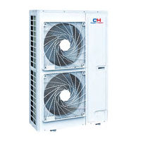
Table of Contents
Table of Contents
5
Safety Instruction
6
General Introduction
8
Outdoor Unit and Indoor Unit Combination
8
Operating Range
8
Before Installation
9
Standard Accessories
9
Installation Location
9
Installation Instruction
11
Physical Dimension of the Outdoor Unit and Mounting Hole
11
Piping Design
14
Oil Return Trap Installation
17
Installation of the Connection Pipe
18
Pressure Check, Vacuum and Additional Refrigerant Charge
22
Electric Wiring
24
Communication Wiring
27
Check Items after Installation and Trial Run
30
Check Items after Installation
30
Trial Run
30
Common Malfunction and Troubleshooting
32
Check before Contacting Service Center
32
Normal Phenomenon
33
Error Display
33
Maintenance
36
Outdoor Heat Exchanger
36
Drain Pipe
36
Check before the Seasonal Use
36
Maintenance after the Seasonal Use
36
Parts Replacement
37
After-Sales Service
38
Advertisement
Related Products
Cooper & Hunter CHV-5SHH120NK
Cooper & Hunter CHV-5SHH140NK
Cooper & Hunter CHV-5SHH160NK
Cooper & Hunter CHV-5S224SNMX
Cooper & Hunter CHV-5S250SNMX
Cooper & Hunter CHV-5S280SNMX
Cooper & Hunter CHV-5S120NK
Cooper & Hunter CHV-5S140NK
Cooper & Hunter CHV-5S160NK
Cooper & Hunter CHV-5S224NMX
Cooper & Hunter Categories
Air Conditioner
Dehumidifier
Heat Pump
Humidifier
Fan
More Cooper & Hunter Manuals
Login
Sign In
OR
Sign in with Facebook
Sign in with Google
Upload manual
Upload from disk
Upload from URL