Sign In
Upload
Manuals
Brands
Continuum Manuals
Measuring Instruments
Precision II Series
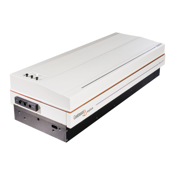
Continuum Precision II Series Instruments Manuals
Manuals and User Guides for Continuum Precision II Series Instruments. We have
1
Continuum Precision II Series Instruments manual available for free PDF download: Operation And Maintenance Manual
Continuum Precision II Series Operation And Maintenance Manual (274 pages)
Brand:
Continuum
| Category:
Measuring Instruments
| Size: 3 MB
Table of Contents
Table of Contents
5
Government and Industry Regulations
13
Laser Safety Precautions
13
Chapter I
13
Optical Safety
14
Electrical Safety
14
Additional Safety Regulation References
15
Warnings and Labels
15
Protection While Working with Lasers
15
Laser Emission Classification
15
Precision II Warning Labels
16
Chapter II System Operation, Rev. B
29
Startup Procedure
29
RB601 Keyboard
29
Shutdown Procedure
30
Programming the RB601 Remote Box
31
Options
32
Second Harmonic Generation
32
Harmonic Stage Assembly
32
Third Harmonic Position
34
Connecting Harmonic to Face Plate
34
Third Harmonic Generation
35
Fourth Harmonic Generation
36
LNE Alignment
37
Fourth Harmonic Position
37
External Triggering of Precision Series
39
Direct Access Triggering (DAT)
39
Precision II Series Chronograph
40
Stanford Research Pulse Generator Setup
41
External Trigger Panel (ETP)
42
Remote RS232 Operation
43
A) Command Protocol
43
B) RS232 Specification/Baud Rate
45
C) RS232 Signals
45
D) Host Computer Demo Program
46
Installation
50
Physical Dimensions Precision II Series
57
Chapter III Subassemblies & Module Descriptions, Rev. B
59
Laser Bench Optics
59
Laser Bench Electronics
64
External Controls
64
Seeder Panel on Side of Bench
67
Wiring Diagrams
73
Laser Bench Mechanics
80
Assy. HP71
80
Built-In Rack Electronics Cabinet
81
Control Unit, CU601C
85
Reactance-Limiting Inductor L
109
CB634C Front & Rear Panels
130
Cooling Group, CG604C
149
CG604C Front & Rear Panels
149
Waterflow Diagram
149
Cooling Requirements 50Hz
152
System Maintenance Schedule
158
Chapter IV Maintenance, Rev. B
159
Cleaning Optics
159
Flashlamp Removal & Replacement
160
Exploded Head Drawings
160
Rod Replacement
162
Replacing the DI Water Filter
165
Bacterial Growth
167
O"Ring Replacement
167
Optical Troubleshooting Chart
175
Chapter V Troubleshooting, Rev. B
178
Electronics Rack Troubleshooting
178
Q-Switch Troubleshooting
180
Burn Pattern Diagram
181
Going to Free-Running
182
Oscillator Alignment Optimization
184
Image as Seen through Rod
185
Oscillator Optimization (with an Oscilloscope)
186
Measuring Oscillator Stability in the Free-Running Mode
187
Eliminating Free-Running
189
Dual Inline Amplifier Alignment Single Rod Head 811-09
192
Alignment Aperture Positions
192
Dual Amplifier IR Alignment
194
Amplifier Alignment Burn Patterns
195
Quartz Rotator Alignment Procedure
196
Amplifier Alignment Single Rod Heads for Precision II 8000
196
Beam Block Position
198
Flashlamp Voltage Adjustment
199
Cooling Group Contamination
200
Chapter VI Parts Lists, Rev. B
203
Electronics & Supplies
208
Optics/Electro-Optics
208
Chapter VII Appendix, Rev. B
211
Express Warranty
211
Limitation of Remedy
211
Disclaimer of Implied Warranty
211
Returns, Adjustments & Servicing
211
Service Information
213
Lightwave™ Seeder Manual
215
Section 1: Overview/Section 2: Installation
220
Injection Seeding Theory
223
Longitudinal Modes of a Standing Wave Resonator
223
Section 1: Overview
223
Q-Switch Buildup Time: Seeded Operation
225
Q-Switch Buildup Time: Unseeded Operation
225
Frequency Control of the Host Laser
226
Suppression of Spatial Hole Burning
228
Frequency Control of the Injection Seeder
229
Frequency Overlap of Seeder and Host Laser
230
Description of Seeder System
231
Seed Laser Source
231
Collimating Lens and Half-Wave Plate
232
Faraday Isolator
232
Q-Switch Build-Up Time Minimization Circuit (Signal Processor)
232
Telescope Assembly
232
Temperature Control and Power Supply Circuits
232
Host Laser Modifications
234
Piezoelectric Frequency Tuning Element
234
Quarter-Wave Plates
234
Elimination of All Secondary Etalon Effects
235
Internal Cooling Water Temperature Stabilization
235
Polarizer Housing Window (Not Shown)
235
Q-Switch Drive Modification
235
List of Terms
236
Safety Summary
236
Laser Emission Levels
237
Safety Features
237
Host Laser Modifications
240
Section 2: Installation
240
Cooling Water Stabilization
241
Marx Bank
241
Vibration Isolation
241
Polarizer Assembly Modifications
242
Quarterwave Waveplate Installation
243
Piezo Installation
244
Mounting
245
Seeder Installation
245
Gross Mirror Alignment
246
Q-Switch Voltage Optimization
246
Frequency Overlap Adjustment
247
Fine Mirror Alignment
249
Control Panel
250
Control Switch
250
Emission Indicator
250
Key Switch
250
Mode Switch
250
Section 3: Operation
250
Frequency BNC
251
Piezo BNC
251
Reset BNC
251
Reset Indicator
251
Build-Up Time BNC
252
Laser Head Control Panel
252
Laser Temperature Leds
252
Diagnostic Connector
253
Diode Current LED
253
Dither Potentiometer
253
Laser Frequency Potentiometer
253
System Status LED
253
Trigger and Photodiode LED
253
Output through an Etalon
254
Pulse Trace Observation
254
System Check
254
System Shutdown
254
System Start up
254
Host Laser Maintenance
256
Section 4: Maintenance
256
Seeder/Host System Service
257
Section 5: Troubleshooting
258
Appendices
261
Appendix I: Product Specifications
262
Appendix II: Footnotes
263
Advertisement
Advertisement
Related Products
Continuum Surelite I 10
Continuum Surelite I 20
Continuum Surelite I 30
Continuum Surelite III 10
Continuum Surelite II 20
Continuum Precision 9000
Continuum Surelite EX 10
Continuum Categories
Pedicure Spa
Water Heater
Measuring Instruments
Amplifier
Accessories
More Continuum Manuals
Login
Sign In
OR
Sign in with Facebook
Sign in with Google
Upload manual
Upload from disk
Upload from URL