Sign In
Upload
Manuals
Brands
Concordia Manuals
Beverage Dispenser
XPRESS
Concordia XPRESS Manuals
Manuals and User Guides for Concordia XPRESS. We have
1
Concordia XPRESS manual available for free PDF download: Technician Manual
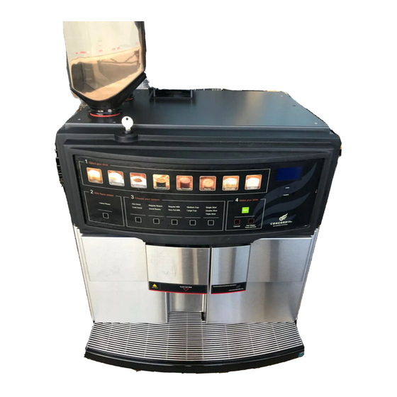
Concordia XPRESS Technician Manual (306 pages)
Brand:
Concordia
| Category:
Beverage Dispenser
| Size: 12 MB
Table of Contents
Table of Contents
4
Section 1 :: Xpress Overview
13
Xpress Overview
14
Xpress Components
15
Flavor System Overview
16
Flavor System Components
17
Section 2 :: Installation and Removal
19
Technical Specifications and Site Requirements
19
Machine Dimensions
21
Installation
22
Configuring the Machine for Supply Voltage
22
Espresso Machine Electrical Settings
22
Setting the DC Jumper Plug
22
Configuring Transformer Auxiliary Connector #1
23
Plumbing
24
Connecting the External Drain
24
Water Supply
24
Problems with Reverse Osmosis Water System
25
Flavor System
25
Flavor System Installation
25
Prime the Flavor System
25
Chocolate Sauce
25
Verify Flavor Pour Rate
25
Additional Tasks Required at Installation
26
Power up the Machine
26
Install Bean Hoppers
26
Install Cup Stand (Optional)
26
Operational Configuration
26
Placing Milk in the Refrigeration Unit
26
Machine Calibration
27
Customer Training
27
Installation Checklist
27
Removal Procedures
27
Section 3 :: Electrical
29
Electrical Block Diagram
30
Fuses
31
Backplane
32
AC Drawer Assembly
33
DC Board Assembly
34
CPU Board
35
Peripheral Connections Configuration
38
Transformer
39
Power into the Machine
43
DC Power Supply Board Leds
46
Heating Element Wiring Diagrams
48
Jumper Plug Connector Detail
49
Section 4 :: Software
55
Software Overview
56
Software Menu Informational Screens
56
Categories
56
Service Switch
57
Navigating the Software Menu
58
Accessing a Sub-Category
58
Exiting the Menu System
59
Accessing the Grand Total Drink Count
59
Accessing Total Drink Count Statistics
59
Accessing Daily Drink Count Statistics
59
Software Quick Reference Table
60
Calibration
67
Calibrating Pump Pressure
68
Calibrating Espresso
68
Configuring the Bean Hoppers
68
Espresso Extraction and Temperature Parameters
69
Drink Temperatures
69
Verifying Espresso Extraction
69
Calibrating Milk Timings
70
Calibrating Brewed Coffee
70
Calibrating Flavor Timings
71
Espresso Extraction Pre-Treatment Options
71
Pre-Treatment Options
71
CPU Board
73
Loading New Software to a Machine
74
Required Equipment
74
Configuring Hyperterminal
74
Connecting a Laptop to a Machine
81
Updating Software for Customers with Custom Drink Recipes
84
Section 5 :: Plumbing
85
The Water System
85
Line Pressure
87
Check Valve
87
Water Filtration System
87
Hot Water Tank
88
Temperature/Level Probe
89
Level Probe
89
Temperature Probe
90
Pressure Relief Valve
90
High Temperature Limit Switch
90
Water Inlet
90
Flowmeter
91
Heating Elements
91
Brew Valve
91
Hot Water Valve
91
Draining the Hot Water Tank
92
Water Pump and Motor
92
Water Pressure Gauge
93
Setting Pump Pressure
93
Expansion Valve
93
Check Water Flow Message
93
The Steam System
94
Steam Tank - Front View
94
Steam Tank - Rear View
95
Steam Tank Fill Valve
96
Steam Tank
96
Water Level Probes
96
Pressure Gauge
97
Heating Elements
97
Pressure Relief Valve
97
High Temperature Limit Switch
97
Steam Valves
98
Left Steam Valve
98
Center Steam Valve
99
Right Steam Valve
99
Air Purge Process
99
Captive Water Purge System
99
Draining the Steam Tank
99
Section 6 :: Coffee System
101
The Coffee System
102
Espresso Path
102
Grinders
103
Double Grinder Assembly
103
Calibration: Espresso Grind
104
Grinder Adjustment Panel
104
Grinder Adjustment Diagram
105
Measuring the Coffee Powder Dose
105
Coffee Powder Channel
106
Removing the Grinder
106
Replacing the Grinder Burrs/Blades
107
Setting the Grinder Adjustment Indicator to MID-Scale
107
Bean Hoppers
108
Filling a Bean Hopper
108
Inserting the Hopper Stopper
108
Removing a Bean Hopper
108
Brew Group
109
Brew Group Initialization
110
Brew Group Components
110
Hall-Effect Sensors
111
Left Piston
112
Right Piston
112
Piston Movement
112
Viewing the Left Piston Movement
113
Removing the Left Piston
113
Removing the Right Piston
114
Gearbox Removal and Installation
115
Removing the Gearbox
115
Installing the Gearbox
116
Section 7 :: Milk System and Refrigeration Unit
117
The Milk Delivery System
118
Milk Delivery System Components
118
Milk Pump Assembly
118
Milk Pick-Up Tube
118
Milk Pump
118
Milk System Theory of Operation
119
Basic Terminology
119
Initial Setup of the Milk System
120
Milk System Capabilities
121
A Common Milk Timing Mistake
121
Air Gate Valve Assembly
121
Air Gate Valves
122
Air Purge Valves
122
Air Vent Needles
122
Connection of Milk Pump Assembly and Air Gate Valve Assembly
122
Alt Milk Valve
122
Steam Delivery Components
123
Steam Valves
123
Mixing TEE Assembly
123
Refrigeration Unit Overview
124
Placing Milk in the Machine
125
Checking the Refrigeration Unit Temperature
125
Refrigeration Cooling Module Assembly
126
Fan Control Board
127
Cold Sink Deflector
127
Interior Circulation Fan Assembly
128
Exterior Cooling Module Fan Assembly
128
Temperature Probe Assembly
128
Milk Weight Trays
129
Adjusting a Milk Weight Tray
131
Milk Level Sensors
132
Auto Milk Select
132
Section 8 :: Steam Wands
133
Steam Wand Overview
134
Automatic Steam Wand
134
Automatic Steam Wand Theory of Operation
134
Automatic Steam Wand Selections
135
Automatic Steam Wand Programming
136
Air Pump
136
Steam and Vacuum Valve Assembly
136
Automatic Steam Wand Wiring
137
Replacing an Automatic Steam Wand
137
Manual Steam Wand
138
Replacing a Manual Steam Wand
138
Removing a Steam Wand
140
Installing a Steam Wand
140
Cleaning a Steam Wand
140
Section 9 :: Flavor System
141
The Flavor System
142
Chocolate Sauce Delivery Path
142
Syrup Delivery Path
143
Flavor Tubes
143
Flavor Storage Area
144
Chocolate Sauce
144
Chocolate Heater Assembly
144
Connecting Flavor Tubing
144
Changing the Flavor Pour Rate
145
Verifying Proper Syrup Flow
146
Changing Flavor Boxes
147
Peristaltic Pumps
148
Syrup Manifold
148
Chocolate Rinse Purge Valve
149
Milk Bowl
149
Removing the Syrup Manifold
149
Replacing the Syrup Manifold
150
Cleaning the Flavor Delivery System
150
Priming the Flavor Delivery System
152
Section 10 :: Vending
153
Vending Overview
154
Vending Backpack
154
Replacing a Card Reader
154
Installing a Vending Unit
155
Removing a Vending Unit
155
Troubleshooting
155
Section 11 :: Cleaning and Maintenance
157
Daily Maintenance
158
Concordia Cleaning Products
158
Cleaning Timers
159
Preventive Maintenance
159
Section 12 :: Concordia Procedures
161
Service Call Process
162
Arrival to Site
162
Machine Repair
162
Hold for Parts Procedures
162
Departing from Site
162
Required Immediately for Call Closeout
163
Complete Call Protocol
163
Machine Appearance
163
Milk System
163
Brew Group
163
Water Tank
163
Water Pump
163
Steam Tank
163
Refrigeration Unit
164
Espresso Extraction
164
Milk Pour
164
Service Call Checklist
165
Parts Return Policy
166
Non-Consignment Agents
166
Consignment Agents
166
Return Material Tag
167
Parts Replenishment Form
168
Section 13 :: Customer Service and Training
169
Training the Customer
170
User Guide
170
Starting and Resetting the Machine
170
Filling Machine with Beans and Milk
170
Pouring Drinks and Cancelling Drinks
170
Restocking and Changing Flavor Boxes
170
Cleaning
171
Serial Number
171
Accessing Software Menu
171
Troubleshooting Tips
171
Contacting Concordia for Assistance
172
Concordia Beverage Systems' Value-Added Service
173
Value-Added Service
174
Greet the Customer
175
Understand Your Customer
176
Empathize with Your Customer
177
Solve the Problem
178
Train the Customer
178
Section 14 :: Messages
179
Troubleshooting Display Messages
180
Section 15 :: Troubleshooting
189
Troubleshooting Quick Reference Guide
190
Machine Failure
190
Coffee System
191
Flavor System
191
Milk System
192
Troubleshooting Trees
193
Brew System: Right Drive Timeout
194
Brew System: Invalid Stop L
195
Brew System: Invalid Stop R
197
Brew System: Left Drive Timeout
199
Grinder System: out of Beans
201
Milk System: Overpouring Milk
203
Milk System: Cold Milk Pour
205
Milk System: no Milk Pour
207
Milk System: Short Milk Pour
209
Refrigeration System: Temperature above 40˚F
211
Steam System: Steam Temperature High
213
Steam System: Check Sensor Voltage
214
Steam System: Check Steam Probes
215
Steam System: Check Steam Tank
216
Steam System: Steam Temperature Low
217
Water System: Water Temperature too High
218
Water System: Water Temperature too Low
219
Water System: Check Water Supply
221
Water System: Water Tank Limit Switch Open
223
Flavor System: Cross-Contamination of Syrup Lines
225
Flavor System: too Much Flavor in Drink
226
Flavor System: Not Enough Flavor in Drink
227
Flavor System: no Flavor in Drink
229
Electrical System: Check Analog Board
231
Electrical System: Incorrect Software for Touchpad
232
Electrical System: Front Panel Failed
234
Electrical System: Check Clock
235
Electrical System: Check Stats
236
Electrical System: CPU Load Disp and Seq Error
237
Electrical System: AC Voltage Error
239
Electrical System: DC Voltage Failure
241
Vending System: Card Swipe or Tap Not Authorized
243
Vending System: Not Configured
244
Vending System: no Display on Card Reader
245
Section 16 :: Parts Lists & Diagrams
247
Recommended Tools List
248
Standard Tools
248
Concordia Stocked Tools
248
Consumables
248
Parts Lists and Diagrams
249
Diagram 1: Machine Overview
250
Diagram 1, Parts List: Machine Overview
251
Diagram 2: Grounds bin Door, Refrigerator Door with Hot Water Button Assembly
252
Diagram 2, Parts List: Refrigerator Door with Hot Water Button Assembly
253
Diagram 3: Refrigerator Door with Steam Wand Assembly
254
Diagram 3, Parts List: Refrigerator Door with Steam Wand Assembly
255
Diagram 4: Front Panel
256
Diagram 4, Parts List: Front Panel
257
Diagram 5: Top Panel
258
Diagram 5, Parts List: Top Panel
259
Diagram 6: Grinder Assembly
260
Diagram 6, Parts List: Grinder Assembly
261
Diagram 7: Grinder Adjustment Assembly
262
Diagram 7, Parts List: Grinder Adjustment Assembly
263
Diagram 8: Group Upper and Lower Piston Assembly
264
Diagram 8, Parts List: Group Upper and Lower Piston Assembly
265
Diagram 9: Group Drive System
266
Diagram 9, Parts List: Group Drive System
267
Diagram 10: Milk Pump Assembly
268
Diagram 10: Parts List, Milk Pump Assembly
269
Diagram 11: Product Delivery Assembly, Xpress 6
270
Diagram 12: Product Delivery Assembly, Xpress 0
270
Diagram 13: Refrigeration Unit Assembly
274
Diagram 13, Parts List: Refrigeration Unit Assembly
275
Diagram 14: Chocolate Sauce Delivery System
276
Diagram 15: Syrup Delivery System
278
Diagram 15, Parts List: Syrup Delivery System
279
Diagram 16: Refrigeration Unit Cooling Assembly
280
Diagram 16, Parts List: Refrigeration Unit Cooling Assembly
281
Diagram 17: Steam Tank, Front
282
Diagram 17, Parts List: Steam Tank, Front
283
Diagram 18: Steam Tank, Rear
284
Diagram 18, Parts List: Steam Tank, Rear
285
Diagram 19: Water Pump and Motor
286
Diagram 19, Parts List: Water Pump and Motor
287
Diagram 20: Hot Water Tank
288
Diagram 20, Parts List: Hot Water Tank
289
Diagram 21: Water/Steam Gauge/ Air Valve Assembly
290
Diagram 21: Parts List: Water/Steam Gauge/Air Valve Assembly
291
Diagram 22, Parts List: Drain Valve Bridge Web Assembly
292
Diagram 22, Parts List: Drain Valve Bridge Web Assembly
293
Section 17 :: Index
295
Advertisement
Advertisement
Related Products
Concordia Xpress series
Concordia Xpress 0
Concordia XpressTouch
Concordia XpressTouch XT
Concordia XpressTouch XT6
Concordia Categories
Coffee Maker
Brewing Systems
Beverage Dispenser
Medical Equipment
More Concordia Manuals
Login
Sign In
OR
Sign in with Facebook
Sign in with Google
Upload manual
Upload from disk
Upload from URL