Sign In
Upload
Manuals
Brands
COBHAM Manuals
Antenna
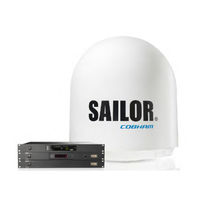
SAILOR Global Xpress Modem Unit GMU
COBHAM SAILOR Global Xpress Modem Unit GMU Manuals
Manuals and User Guides for COBHAM SAILOR Global Xpress Modem Unit GMU. We have
1
COBHAM SAILOR Global Xpress Modem Unit GMU manual available for free PDF download: Installation Manual
COBHAM SAILOR Global Xpress Modem Unit GMU Installation Manual (168 pages)
Brand:
COBHAM
| Category:
Antenna
| Size: 11 MB
Table of Contents
Installation Wizard
2
Distance to Other Equipment
5
Microwave Radiation Hazards
5
No-Transmit Zones
5
Safety Summary
5
Compass Safe Distance
6
Grounding, Cables and Connections
7
About this Manual
8
Table of Contents
10
Chapter 1 Introduction
12
SAILOR XTR Ka System
12
System Overview
12
Product View
13
System Features
13
Above Deck Unit (ADU)
14
Service Friendly System
14
Modules in the ADU (100 CM)
15
Modules in the ADU (60 CM)
17
Below Deck Unit (BDU)
18
GX Modem Unit (Modem)
19
Part Numbers and Options
20
Chapter 2 Installation
21
Initial Inspection
21
To Unpack
21
What’s in the Box
21
Site Considerations
22
Tools Needed
22
Transport of the Antenna
22
Modifying the Radome or Using Another Radome
23
Painting the Radome
23
Safe Access to the ADU: Radiation Hazard
23
Obstructions (ADU Shadowing)
24
Ship Motion and Offset from the Ship’s Motion Centre
24
Blocking Zones – Azimuth and Elevation
25
ADU Mast Flange and Mast Length
26
ADU Mast Flange (100 CM)
27
ADU Mast Flange (60 CM)
28
Mast Length and Diameter
29
Mast Length (100 CM)
30
Mast Dimensions with 2 Braces
31
Mast Dimensions Without Braces
31
Mast Dimensions with 3 Braces
32
Mast Length 60 CM
33
Mast with Three Brace
33
Mast Without Braces
33
Maximum Mast Length for a Mast Without Braces (60 CM)
33
Mast with Three Braces (60 CM)
34
Maximum Mast Length and Connection Point for a Mast with Three Braces
35
Minimum Brace Outer Diameter
35
Interference from Radar, GPS/GNSS, L-Band and Other Transmitters
36
Radar
36
Condensation and Water Intrusion
38
Drain Tube with Free Space View
38
Alternative ADU Cable
39
Antenna Cable Data
39
Installation of the ADU (100 CM)
40
Connecting the ADU Cable
42
Maximum Allowed RF Loss in the ADU Cable
42
Mounting the ADU on the Mast Flange
42
ADU, Bolt for Optimum Grounding
43
To Ground the ADU
43
To Open the Service Hatch
43
Installation of the ADU (60 CM)
44
To Install the ADU
45
Installation of the BDU
48
Installation of the Modem
48
To Ground the BDU
48
To Connect the ADU, BDU and Modem
49
To Ground the Modem
49
Communication
50
Integration of a 3Rd Party IP Device (100 CM)
50
Power Connector
50
Example of a 3Rd Party Device Integration
51
Mechanical Interface
51
Power and Startup
52
Power Cycle
52
AC Input Connector
53
ADU Connector
53
Chapter 3 Interfaces
53
Connector Panel of the BDU
53
NMEA 0183 RJ-45 Connector
54
Rx/Tx Connectors for Modem
54
GPIO RJ-45 Connector
55
RS-232 RJ-45 Connector
56
RS-422 RJ-45 Connector
56
Connector Panel
57
Interfaces of the Modem
57
LAN Connectors
57
Rx in and Tx out Connectors
57
RS-232 and RS-422 Connectors
58
I/O Connector for Tx Mute and Rx Lock (Future Use)
59
LAN Connectors (8 + 2)
59
Chapter 4 Setup of the Antenna
60
Introduction to the Web Interface
61
Sections on the Dashboard
62
Top Bar
64
Settings
65
VSAT Profiles
65
Modem Types
66
SAILOR GX Modem (GMU)
66
Elevation TX Cutoff Versus VSAT Modem Bandwidth and Power
67
Generic Modem
67
DHCP Server Settings
69
DNS Setup
69
Network Settings
69
Static IP or DHCP Client
69
ADU Port Setup
70
Navigation
70
Heading Input: None
72
Inclined Orbit Satellites
72
Operation in Gyro-Free Mode
72
Tracking for Satellite Elevation between 5 and 75 Degrees
72
Acquisition Process and Search Pattern
73
Tracking for Satellite Elevation above 75 Degrees
73
With Heading Input or Fixed Heading
73
Acquisition Times
74
Blocking Zones
74
Without Heading Input and Not Fixed Heading (Gyro-Free)
74
Blocking Map for Optimization of Blocking Zones
75
E-Mail Setup (Secure E-Mail)
76
Iot & Management
76
Remote Syslog
77
Snmp
77
Diagnostics Report
78
Telnet Access
78
Statistics Report
79
Dual Antenna
81
Iot Hub Configuration
81
Processing the Statistics Report in a Spreadsheet Application
81
To Change a Password
82
To Set up Permissions for Guest User
82
User Administration
82
Service
85
Software
85
Upload
85
Software Recovery Procedure (Safe Mode)
86
To Import and Export a System Configuration
86
BDU Config (Save Antenna Settings in the BDU)
87
Calibration
87
Factory Default
87
Automatic Azimuth Calibration with an Active VSAT Profile
88
Azimuth Calibration
88
Azimuth Calibration (User Controlled)
89
Cable Calibration
90
Manual OTC (BUC Calibration) and GX Modem Access
90
Manual One Touch Commissioning (OTC)
91
Line up
92
Modem Access Configuration (Port Forwarding)
92
Fixed TX Gain Principle
93
Events
94
Support
94
BDU Display and Keypad
95
Keypad and Menus of the BDU
95
Adjusting Brightness of the Display
96
List of Menus
96
Navigating the Menus
96
Antenna Menu of the BDU
97
Modem Menu of the BDU
97
Network Menu of the BDU
97
Events Menu of the BDU
98
Satellite Menu of the BDU
98
Startup Sequence
99
Chapter 5 Installation Check Lists
100
Installation Check List: Antenna
100
Installation Check List: BDU, Connectors and Wiring
101
Installation Check List: Functional Test in Harbor
102
Built-In Test and Leds
103
Chapter 6 Service
103
Leds of the Modules in the ADU
103
Leds in the BDU
104
Removal and Replacement of ADU Modules
104
Removal and Replacement of the BDU
104
Administrator Password Forgotten
105
To Verify that the Antenna Can Go into Tracking Mode
105
Troubleshooting Basics
105
Returning Units for Repair
106
Appendix A Technical Specifications
107
Specifications (100 CM Antenna
108
Specifications (60 CM Antenna
110
Patents
112
Outline Drawings
113
Appendix B Dual Antenna Solution
117
Installation of the Dual Antenna Solution
117
Introduction
117
To Install the Dual Antennas
119
Configuration of the Dual Antenna Solution
120
To Configure the Master BDU
121
To Configure the Slave BDU
121
Blocking Zone Setup for Dual Antenna Setup
122
To Make an OTC for Dual Antenna Systems
123
Flow Chart for Installation of the Dual Antenna Solution
124
Dual Antenna Splitter Cable
125
Appendix C Miscellaneous
126
Better Blockage Communication
126
Encountering Blockage, Configured with Multiple Satellites
126
Performance Optimization for Blockage
126
Minimum Elevation Angle
127
Appendix D Command Line Interface
128
SSH Connection
128
Supported Connection Modes
128
Telnet Connection
128
List of Commands
129
ESD Protection
134
Introduction to Grounding
134
Reasons for Grounding
134
RF Interference
134
Grounding Recommendations
135
To Extend the Ground Plane
135
Alternative Grounding for Steel Hulls
136
Alternative Grounding for Aluminum Hulls
137
Terminal Grounded at a Dedicated RF Ground
137
Terminal Grounded at the Hull
137
Alternative Grounding for Fiber Glass Hulls
138
Ground Cable - Construction
139
Separate Ground Cable
139
Ground Cable - Connection
140
Isolation of the ADU from the Mounting Base
141
Jumper Cable for Grounding
142
Appendix F Event Messages
143
Overview
143
List of Events
144
Appendix G Inmarsat GX Satellites
156
Appendix H Approvals
157
Ce (Red
157
Inmarsat Type Approval
158
Abbreviations
159
Index
161
Advertisement
Advertisement
Related Products
COBHAM Sea Tel
COBHAM SAILOR 900 Viasat Ka
COBHAM Sea Tel Tracker 6000
COBHAM S-67-175992
COBHAM S-67-175993
COBHAM SAILOR 1000 XTR Ka 4.5W ADU
COBHAM SAILOR 1000 XTR Ka 9.0 ADU
COBHAM SAILOR XTR BDU
COBHAM SAILOR XTR Ku
COBHAM SAILOR Fleet One
COBHAM Categories
Antenna
Marine Equipment
Radio
Touch terminals
Receiver
More COBHAM Manuals
Login
Sign In
OR
Sign in with Facebook
Sign in with Google
Upload manual
Upload from disk
Upload from URL