Sign In
Upload
Manuals
Brands
CleaverBrooks Manuals
Boiler
4WI
CleaverBrooks 4WI Manuals
Manuals and User Guides for CleaverBrooks 4WI. We have
1
CleaverBrooks 4WI manual available for free PDF download: Operation, Service And Parts Manual
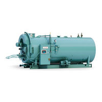
CleaverBrooks 4WI Operation, Service And Parts Manual (216 pages)
Promethean Boilers
Brand:
CleaverBrooks
| Category:
Boiler
| Size: 8 MB
Table of Contents
Table of Contents
7
CHAPTER 1 Firetube Operation Basics
15
Overview
15
The Boiler
17
Construction
18
Steam Controls (All Fuels)
19
Controls
19
Low Water Cutoff
19
Water Column
20
Steam Pressure Gauge and ALWCO
20
Safety Valve(S)
20
Hot Water Controls (All Fuels)
21
Pressure and Temperature Gauges
21
Controls
21
Low Water Cutoff and ALWCO
22
Safety Valve(S)
22
IFGR Components
22
CHAPTER 2 Burner Operation and Control
25
The Burner
25
Controls Common to All Boilers
26
Control and Component Function
27
Components Common to All Boilers
27
Controls for Gas Firing
30
Controls Common to Oil-Fired Boilers (Including Combination)
32
Additional Controls for Heavy Oil
35
Controls for Combination Burners Only
37
Combustion Air
38
Automatic Ignition
38
Atomizing Air
39
Oil Fuel Flow: Light Oil
40
Oil Fuel Flow: Heavy Oil
41
Gas Fuel Flow
43
Modulating Firing
44
CHAPTER 3 Waterside Care and Requirements
47
Overview
47
Water Requirements
48
Hot Water Boilers
48
Air Removal
48
Minimum Water Temperature
48
Rapid Replacement of Boiler Water
48
Continuous Flow through the Boiler
49
Water Circulation
50
Multiple Boiler Installations
50
Pump Location
51
Pump Operation
51
Pressure
51
Steam Boiler
52
Feed Pump Operation
52
Water Feeder (Optional) Operation
52
Water Treatment
52
Cleaning
53
Hot Water and Steam Piping
53
Pressure Vessel
53
Boil-Out of a New Unit
54
Washing out
56
Hot Water Boiler
56
Steam Boiler
56
Blowdown: Steam Boiler
57
Types of Blowdown
57
Intermittent Manual Bottom Blowdown
57
Continuous Blowdown (Controlling TDS)
58
Frequency of Manual Blowdown
58
Manual Blowdown Procedure
59
Periodic Inspection
59
Preparation for Extended Layup
60
CHAPTER 4 Sequence of Operation
63
Overview
63
Circuit and Interlock Controls
64
Sequence of Operation: Gas or Oil
65
Pre-Purge Cycle
65
Ignition Cycle
66
Run Cycle
66
Flame Loss Sequence
67
CHAPTER 5 Starting and Operating Instructions
71
General Preparation for Startup: All Fuels
71
Control Settings: Steam and Hot Water
72
Gas Pilot
74
Revised 2009)
74
Atomizing Air
74
Firing Preparations for No. 2 Oil (Series 100-200)
75
Firing Preparation for No. 6 Oil (Series 400-600)
77
Oil Flow
78
Oil Pressure
78
Oil Temperature
79
Firing Preparations for Gas (Series 200-400-700)
80
IFGR Setup
81
Startup, Operating, and Shutdown: All Fuels
82
Operating
85
Shutdown
85
Control Operational Test and Checks
85
CHAPTER 6 Adjustment Procedures
87
Overview
87
Linkage: Modulating Motor and Air Damper
88
Modulating Motor
90
Modulating Motor Switches: Low-Fire and High-Fire
90
Burner Operating Controls: General
90
Modulating Pressure Control: Steam
94
Operating Limit Pressure Control: Steam
94
High Limit Pressure Control: Steam
95
Modulating Temperature Control: Hot Water
95
High Limit Temperature Control: Hot Water
95
Operating Limit Temperature Control: Hot Water
95
Low Water Cutoff Devices: Steam and Hot Water
96
Combustion Air Proving Switch
96
Atomizing Air Proving Switch
97
Gas Pilot Flame Adjustment
97
Gas Pressure and Flow Information
99
Pressure
99
Gas Flow
101
Pressure Correction
101
Checking Gas Flow
103
Gas Fuel Combustion Adjustment
104
Burner Low-Fire Adjustment
106
Low-Gas-Pressure Switch
107
High-Gas-Pressure Switch
107
Fuel Oil Pressure and Temperature: General
107
Fuel Oil Combustion Adjustment
109
Standard Burner Low-Fire Adjustment 100-200 HP
110
Burner Low-Fire Adjustment 250-800 HP
110
Burner Drawer Adjustment
110
Oil Drawer Switch
112
Low-Oil-Temperature Switch: Heavy Oil
112
High-Oil-Temperature Switch: Optional
112
Low-Oil-Pressure Switch: Optional
112
Electric Oil Heater Thermostat: 400 and 600 Series (Steam)
112
Steam Oil Heater Thermostat: No. 6 Oil, 400 and 600 Series (Steam)
113
Revised 2009)
114
CHAPTER 7 Troubleshooting
115
Introduction
115
CHAPTER 8 Inspection and Maintenance
119
Overview
119
Periodic Inspection
120
Fireside Cleaning
121
Water Level Controls
122
Steam Boiler
122
Hot Water Boiler
123
Water Gauge Glass
123
Electrical Controls
124
Flame Safety Control
126
Checking Pilot Flame Failure
127
Checking Failure to Light Main Flame
128
Checking Loss of Flame
128
Oil Burner Maintenance
129
Light Oil Strainers
129
Heavy Oil Strainers
129
Cleaning the Oil Nozzle
130
Cleaning Air Purge Nozzle (No. 6 Oil) and Back Pressure Orifice Nozzle (No. 2 Oil)
130
Ignition System
131
Gas Burner Maintenance
132
Motorized Gas Valve
133
Solenoid Valves
133
Air Control Damper, Linkage and Cam Spring
134
Fan/Motor Cassette Removal
135
Inspection and Adjustment
136
Fan/Motor Cassette Installation
137
Safety Valves
138
Fuel Oil Metering Valve, Adjusting and Relief Valves
139
Air Pump and Lubricating System
141
Air Pump
141
Lubricating Oil
141
Lubricating Oil Strainer and Cooling Coil
142
Air-Oil Tank
142
Air Cleaner
142
Lube Oil Cooling Coil
143
Flexible Coupling Alignment
143
Air Compressor Replacement
144
Dismantling
144
Reassembly
145
Refractory
145
Furnace Liner
146
Throat Tile and Liner
147
Installation
147
Rear Door
149
Opening and Closing Doors
149
Opening Front or Rear Door
149
Rear Access Plug
150
Closing and Sealing Doors
150
Lubrication
151
Electric Motors
151
Control Linkage
151
Solenoid and Motorized Valves
152
IFGR Lubrication
152
Oil Heaters: Electric, Steam, Hot Water
152
Combustion
153
CHAPTER 9 Parts
155
Ordering Parts
155
Revised 2009)
156
Parts
156
Front Door Insulated Head
156
Front Door Exterior Insulation Component List
157
Rear Door Insulated Assembly
158
Rear Door Insulation Component List
159
Rear Door Insulated Access Plug
160
Front Head Assembly 60" Diameter
161
Front Davit Assembly
162
Rear Door Davit Parts List
163
Refractory Throat Materials for 60
164
Refractory Throat Materials 67"-106
165
Motor Cartridge Assembly: 60
166
Motor Cartridge Assembly: 67
167
Motor Cartridge Assembly: 78
168
Motor Cartridge Assembly: 85
169
Motor Cartridge Assembly: 96
170
Motor Cartridge Assembly: 106
171
Front Head Linkage: 60"-106
172
Front Head, FGR Linkage: 60"-85
174
Front Head, FGR Linkage: 96" & 106
176
60" Burner Drawer, Gas Pilot, Models 100-600, 100-125 HP
178
67" Burner Drawer, Gas Pilot, Models 101-600, 150-200 HP
180
78" Burner Drawer, Gas Pilot, HI-TD, 250-300 HP
182
85" Burner Drawer, Gas Pilot, Models 100-200, 350-400 HP
184
96"-106" Burner Drawer, Gas Pilot, Models 101 & 200, 500-800 HP
186
Burner Housing Support: 60
188
Burner Housing Support: 67"-106
190
General Control Panel: 60"-106", 100-800 HP
192
Entrance Box & Fuses: 60"-1-6", 100-800 HP
193
Main Gas Train: 60"-106", 100-800 HP
196
Pilot Gas Train: 60"-106", 100-800 HP
197
Front Head #2 Oil/Air Piping: 60"-67", 100-200 HP
198
Front Head #2 Oil/Air Piping: 78"-85", 250-400 HP
199
Front Head #2 Oil/Air Piping: 96"-106", 500-800 HP
200
Air Compressor Piping: 60"-106", 100-800 HP
201
Air Compressor: 60"-85", 100-400 HP
202
Air Compressor: 96"-106", 500-800 HP
203
Light Oil Piping: 78"-106", 250-800 HP
204
Light Oil Piping: 60"-67", 100-200 HP
205
Hot Water Temperature Controls: 60"-106", 100-800 HP
206
Steam Pressure Controls: 60"-106", 100-800 HP
207
Water Column Piping: 60"-67", 100-200 HP
208
Water Column Piping: 78"-85", 250-400 HP
210
Water Column Piping: 96"-106", 500-800 HP
212
Front Door 60"-106" Air Duct Gasket
214
Pressure Vessel Manway Components
215
Pressure Vessel Handhole Components
215
Advertisement
Advertisement
Related Products
CleaverBrooks 5
CleaverBrooks CB
CleaverBrooks CB100
CleaverBrooks CB100A
CleaverBrooks CB1025A
CleaverBrooks CB50
CleaverBrooks CB60
CleaverBrooks CB70
CleaverBrooks CB80
CleaverBrooks CBEX Elite
CleaverBrooks Categories
Boiler
Burner
Control Unit
Control Panel
Boiler Supplies
More CleaverBrooks Manuals
Login
Sign In
OR
Sign in with Facebook
Sign in with Google
Upload manual
Upload from disk
Upload from URL