Sign In
Upload
Manuals
Brands
Cleaver-Brooks Manuals
Boiler
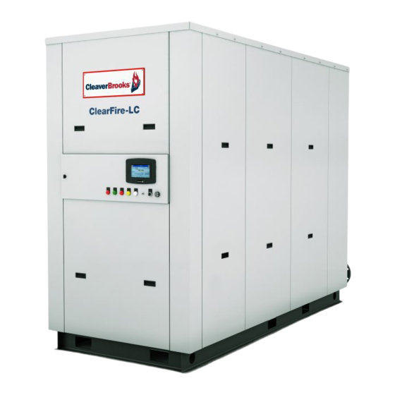
ClearFire CFLC-5000
Cleaver-Brooks ClearFire CFLC-5000 Manuals
Manuals and User Guides for Cleaver-Brooks ClearFire CFLC-5000. We have
1
Cleaver-Brooks ClearFire CFLC-5000 manual available for free PDF download: Operation And Maintenance Manual
Cleaver-Brooks ClearFire CFLC-5000 Operation And Maintenance Manual (291 pages)
Condensing Boiler 4,000-12,000 MBTU
Brand:
Cleaver-Brooks
| Category:
Boiler
| Size: 12 MB
Table of Contents
What to Do if You Smell Gas
2
Table of Contents
5
Section 1 Introduction
7
Compact Firetube Design
8
High Efficiency
8
Advanced Construction
8
CFLC Features and Benefits
8
Standard Equipment
8
The Burner
9
Burner Gas Train
9
Controls
9
Gas Train
9
Variable Speed Drive
10
Component/Connection Locations
10
Control Panel Interior
10
VSD (Cutaway View)
10
CFLC Cutaway
11
Boiler Safety Valve(S) & Air Vent
11
Return Temperature Sensor (Rear Casing & Insulation Not Shown)
12
Stack Outlet, Water Outlet, and Combustion Air Inlet
12
Optional Equipment
13
Installation
15
Section 2 Installation
16
Boiler Assembly and Placement
17
Lifting and Moving the Boiler
17
Boiler Placement
18
Clearance Required (Inches)
18
Boiler Room
19
Flue Gas/Combustion Air
19
Flue Gas / Combustion Air
19
Water Treatment
19
Boiler Flush
20
Using Glycol
20
Glycol Application Guideline
21
Notes/Limitations
21
Gas Connections
22
General
22
Gas Train Components
22
CFLC Gas Train (Typical)
22
Gas Pressure Requirements
23
CFLC Gas Pressure Requirements
23
Pilot Train
23
Gas Piping
24
Gas Supply Pipe Sizing
25
Gas Line Capacity - Schedule 40 Metallic Pipe
26
Gas Header
27
Gas Header Piping
27
Boiler Water Piping
28
Safety Valve
28
Safety Relief Valve Piped to Safe Point of Discharge
28
Dual Return Design
28
Pressure Drop Curves
29
Dual Returns
29
Pressure Drop Curves, CFLC
30
CFLC Flow Rates
31
Minimum Boiler Overpressure
32
Model CFLC Minimum over Pressure Requirements (100% Water)
32
Condensate Removal and Treatment
32
Condensate Piped Direct to Drain
33
Condensate Tank Setup Options
33
Condensate Treatment Tank - External
34
Condensate Treatment Tank - Internal
34
CFLC Max Condensation
34
Electrical Connections
35
Electrical Connections CFLC
36
Wiring Diagram
37
CFLC 6000 - 12000 Wiring Diagram, Single Fuel (Typical)
37
Stack and Intake Vent Sizing and Installation
39
Venting Connections - General
40
Appliance Categories
40
Flue Venting System Design
40
Section 3 Stack and Intake Vent Sizing and Installation
40
Draft Tolerances
41
Vent Terminal Location
41
Vent Terminations
41
Venting Installation Tips
43
Support Piping
43
Vertical Venting / Inside Combustion Air
44
Vertical Venting / Direct Vent or Sealed Combustion Air
45
Venting for Multiple Units
46
Combustion Air / Boiler Room Ventilation Requirements
48
Combustion Air Methods
48
Air Supply - Unconfined Spaces
49
Two Opening Outside Wall Method
50
Two Opening Ducted Method
51
Air Supply - Engineered Method
52
One Opening Method
52
Two Opening Engineered Method
53
Boiler Room Air
53
Direct Venting/Sealed Combustion
54
Optional Direct Vent/Sealed Combustion Kit
54
Commissioning
57
Operating Conditions
58
Filling Boiler
58
Control Setpoints
58
Section 4 Commissioning
58
Commissioning
58
Model CFLC Boiler / Burner Controller
59
Opening Control Panel
59
Controller Status Leds and Reset Button
59
Falcon Display/Operator Interface
60
Home Page
60
Status Page
60
Operation Page
61
Lockouts, Holds, and Alerts
62
Falcon Display/Interface Page Flow
62
Controller Configuration
63
Changing Falcon Parameter Settings
63
Alarm Banner
63
Configuration Menu
64
Safety Parameters
64
Confirming Safety Parameter Changes
65
Variable Speed Drive Settings
65
Program Module
65
Burner Sequence
66
Basic Burner Sequencing (Central Heat)
66
Fan Speed Settings
66
Initial Start-Up Procedure
66
Premix Burner Technology - Full Modulation
67
Power-Up
68
Operation Check
68
Lgps
68
Annunciation Screen
68
Caps
69
HGPS and GAS VALVE
69
Ignition Failure Check
69
Pilot Fail Check
69
Low Water Cutoff Check
70
Low and High Fire Adjustments
70
Modulation off Point
70
Gas Valve Adjustments
70
Setting Combustion
71
Operation Screen
72
High Air Pressure Switch Settings
73
HAPS Settings
73
Limit Controls Check
73
Post Start-Up Checkout Procedure
73
Falcon Control Functions and Customer Interface
74
Remote Enable and Remote 4-20Ma Input
74
Rate Limiting/Override
75
Configurable Pump/Aux Relay Contacts
76
Annunciator
76
Lead/Lag Control (up to Eight Boilers)
76
Modbus Communication
76
Service and Maintenance
77
Disassembly for Inspection
78
Section 5 Service and Maintenance
78
Front Fireside Access
79
Rear Fireside Access
79
Reassembly
80
Ignition and Flame Detection Systems
80
Ignition Electrode
80
Pilot and UV Scanner
81
Electrode Spacing CFLC
81
Troubleshooting
82
Lockout Conditions
82
Lockout 79 Outlet Temperature High Limit
82
Light-Off Problems
82
Troubleshooting Chart
83
Extended Shutdown
84
Emergency Shutdown
84
Parts
85
Recommended Spare Parts List Model CFLC
86
Section 6 Parts
86
Boiler Mechanical Assembly CFLC 4000/5000
87
Boiler Mechanical Assembly CFLC 6000/8000
88
Boiler Mechanical Assembly CFLC 10000/12000
89
Burner Assembly
89
Burner Assembly CFLC 4000/5000
90
Burner Assembly CFLC 6000/8000
91
Burner Assembly CFLC 10 000/12 000
92
UV Scanner
92
Gas Train CFLC 4000/5000 (Standard 20 PPM Nox)
93
Gas Train CFLC 6000/8000 (Standard 20 PPM Nox)
94
Gas Train CFLC 6000/8000 (Optional 9 PPM Nox)
95
Gas Train CFLC 10000/12000 (Standard 20 PPM Nox)
96
Gas Train CFLC 10000/12000 (Optional 9 PPM Nox)
97
Gas Train CFLC 4000/5000 Propane
98
Gas Train CFLC 6000/8000 Propane
99
Gas Train CFLC 10000/12000 Propane
100
Dual Fuel Gas Trains
101
Gas Train CFLC 10000/12000 Propane
101
Dual Fuel 4000-5000
102
Dual Fuel Nat. Gas 6000-12000
103
Pilot Gas Train
104
Control Panel
105
Cables and Cable Harness
106
Cable Harness Layout
106
Casing & Insulation 4000-5000
107
Casing & Insulation 6000-8000
109
Casing & Insulation 10000-12000
111
Optional Parts
113
Appendix A - Falcon Parameters
115
A-1 CFLC Falcon Parameters
117
Variable Speed Drive Parameters
123
PF 400 Integral Keypad
125
VSD Keypad Functions - PF 400
125
Appendix B - VSD Parameters
125
PF 400 LED Status Indicators
126
VSD LED Indicators - PF 400
126
VSD LCD Display - PF 400
126
Viewing and Editing Drive Parameters - PF 400
127
Editing VSD Parameters - PF 400
127
Drive Parameter List - PF 400
128
CFLC VSD Parameters - PF400
128
PF 525 Display, Control, and Navigation Keys
132
Powerflex 525 Embedded Ethernet/Ip Indicators
132
Viewing and Editing Drive Parameters - PF 525
133
Editing VSD Parameters - PF 525
133
Drive Parameter List - PF 525
134
CFLC VSD Parameters - PF 525
134
Appendix C - Gas Valve
145
Application
148
Ordering Information
148
Accessories
149
Product Numbers
149
Specifications
150
Description
159
Features
159
Approvals
169
Explanation of Symbols
169
Specification
170
Power Consumption Table
170
Mounting
171
Installation Position
171
SE Versions Ending in S22/S82/S302
171
Painting Valve
172
Protection from Radiant Heat
172
Electrical DIN Connector Ratings
173
Initial Setup
173
DIN Connector
173
Electrical DIN Connector Assembly & Wiring
174
MBC Overview & Impulse Lines
175
External Impulse Line (Option)
176
Assembly Instructions
176
Outlet Pressure
177
Low Fire Setting Using MBC Regulator
177
High Fire Setting Using Shutter
177
Changing Coil
178
Internal Filter
180
Test Ports
181
Pressure Taps
181
Valve Leakage Decay Test
182
Preparation for Leak Testing
182
Procedure for Testing Valve #1
182
After Completing the above Tests
182
Valve Leakage Bubble Test (Altern. Method)
183
Leak Test Procedure
183
Flow Cu Rve
184
Appendix D - Falcon Alert, Hold, and Lockout Codes
187
Falcon Holds and Lockouts
189
Falcon Alerts
195
Falcon Lead/Lag
209
Installation and Startup
211
Introduction
211
Appendix E Falcon Lead Lag
211
Appendix F - Falcon Program Module
211
Hydronic Systems
212
Steam Systems
212
System Requirements
212
Header Press. Transmitter (Steam)
218
Outdoor Temperature Sensor
218
Sensor Configuration (Steam)
218
Connecting to a Building Energy Management System
219
Lead Lag Master Configuration
219
Lead Lag Master Configuration Parameters (Hydronic)
220
Lead Lag Master Configuration Parameters (Steam)
220
Lead Lag Master Configuration Parameters - Advanced Settings, Hydronic
220
Demand Switch
223
Lead Lag Slave Configuration
223
On, off Hysteresis
223
PID Gain
223
Copying Parameters to Remaining Slaves
224
Lead Lag Slave Configuration Parameters
224
Loading a PIM
225
Enable Master
226
Outdoor Reset Configuration
226
Monitoring System Performance
227
ODR Curve
227
Startup
227
To Start the Lead Lag System
227
Lead Lag Home Page
228
Example Systems
229
Falcon LL with EMS for Remote Enable/Remote Setpoint
231
Falcon Lead Lag with EMS for Remote Comms/Monitoring
232
Typical Steam System
233
Isolation Valve Control
234
Primary Pumping
234
System Pump Enable (Optional)
234
Primary/Secondary Piping
235
Primary with Dedicated System/Boiler Pumps
236
Domestic Hot Water Priority on Slave
237
Pump Control Block (Pcb) Examples
238
Boiler Pump
239
DHW Pump
240
Central Heat Pump
241
Aux 1 Pump
242
Aux 2 Pump
243
Boiler Wiring Diagrams
244
Model CFC Clearfire Condensing Boiler
244
Model CFW Clearfire Hydronic Boiler
245
Model CFV/CFH Clearfire Steam Boiler
246
General Description of the Lead Lag Application
247
Lead Lag (Ll) Master General Operation
247
Lead Lag Operation
247
Assumptions
248
System Wiring Hookup
250
Typical Falcon L/L Wiring with 4 Slaves
250
Basic Operation
251
Field Installation Configuration
251
Lead-Lag Operation
251
Rotation
251
LL Slave
252
Slave Data Supporting Lead Lag
252
Slave Operation and Setup
252
Aux Pump X, Y, and Z
253
Firing for Local Frost Protection
253
Frost Protection Requests
253
Slave Parameters
253
Ll Master Operation and Setup
254
Slave Mode: Use First, Equalize Runtime, Use Last
254
Slave Sequence Order: 0-255
254
Overall Control
255
Periodic Data Polling Messages
255
Slave Control
255
Data Poll Response Handling
256
Features Common to All States
256
Slave Status Manager
256
Valid Response Message
256
Demand and Priority
257
Slavestate States
257
CH Demand
258
Frost Protection
258
Priority Control
258
Warm Weather Shutdown
258
Master Active Service
259
Master Heat Demand
259
Master Service Status
259
Master Status
259
Modulation Sensor
260
Setpoints
260
Ll Ch Odr Minimum Water Temperature: Degrees or None
261
Ll Ch Tod Setpoint: Degrees or None
261
Outdoor Reset and Boost (Boost Is Future)
261
Time of Day
261
Demand and Rate
262
Integrator Compensation
262
Lead Lag Pid
262
Rate Adjustment
262
Common Features
263
Lead Lag Burner Demand
263
Rate Allocation
263
Rate Allocation Parameters
263
Modulating Stage
264
Parallel Common-Base Limited
264
Rate Allocation Methods
264
Stager
264
Burner Demand
266
Stager Parameters
266
Stager States
266
Add Stage Methods
267
Add-Stage Methods
267
Adding Stages Parameters
267
Add-Stage Condition
268
Drop Stage Methods
268
Dropping Stages Parameters
268
Rate Threshold
268
Boiler off Options
269
Drop-Stage Methods
269
Error Threshold
269
Lead Drop-Stage on Error - Ldse
270
Sequencer
270
Sequencer Parameters
270
Sequencer Add Boiler Selection
271
Sequencer Ordering Function
271
Voluntary Lead Rotation
271
Forced Lead Rotation:
272
Sequencer 1 Minute Event
272
Sequencer Drop Lag Boiler Selection
272
Slave Write: Data
272
Building Energy Management System (EMS) Interface
273
Modbus
273
Wiring
273
Enabling Modbus Communications
274
Interface
274
Physical Layer
274
Application Layer
275
RS-485 Message Format
275
Modbus Registers
276
Product Data
285
Button Actions
286
Operation
286
Backup Data
287
Backup Data Settings
287
Advertisement
Advertisement
Related Products
Cleaver-Brooks ClearFire CFLC-4000
Cleaver-Brooks ClearFire CFLC-6000
Cleaver-Brooks ClearFire CFLC-10000
Cleaver-Brooks ClearFire CFLC-12000
Cleaver-Brooks ClearFire CFLC-8000
Cleaver-Brooks CFV
Cleaver-Brooks CBH Series
Cleaver-Brooks CBH 30
Cleaver-Brooks CBH 70
Cleaver-Brooks CBH 40
Cleaver-Brooks Categories
Boiler
Burner
Control Unit
Control Systems
Industrial Equipment
More Cleaver-Brooks Manuals
Login
Sign In
OR
Sign in with Facebook
Sign in with Google
Upload manual
Upload from disk
Upload from URL