Sign In
Upload
Manuals
Brands
Circutor Manuals
Multimeter
DHC-96 CPM
User Manuals: Circutor DHC-96 CPM Digital Multimeter
Manuals and User Guides for Circutor DHC-96 CPM Digital Multimeter. We have
2
Circutor DHC-96 CPM Digital Multimeter manuals available for free PDF download: Instruction Manual
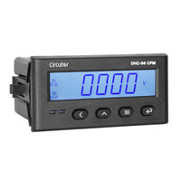
Circutor DHC-96 CPM Instruction Manual (62 pages)
DC Multimeter
Brand:
Circutor
| Category:
Multimeter
| Size: 10 MB
Table of Contents
Safety Precautions
3
Disclaimer
3
Table of Contents
4
Contents
4
Revision Log
6
Symbols
6
1�- Verification Upon Reception
7
2�- Product Description
7
3�- Device Installation
9
3�1�- Prior Recommendations
9
3�2�- Installation
10
3�3�- Device Terminals
11
3�4�- Connection Diagram
12
Installation
12
Installation
13
3�4�3�- Dhc-96 Cpm-Hs: Current Measurement Using Hall Effect Sensor
14
4�- Operation
15
4�1�- Display
15
4�2�- Keyboard Functions
15
4�3�- Relay Outputs
16
4�4�- Analog Output
16
4�5�- Digital Inputs
16
4�6�- Display
17
4�6�1�- Maximum & Minimum Values
18
4�6�2�- Totalisers
18
5�- Configuration
19
5�1�- Configuration of the Input
21
5�1�1�- Voltage Display Value
22
5�1�2�- Voltage Measurement Range
22
5�1�3�- Current Display Value
23
5�1�4�- Current Input
23
5�1�5�- Shunt Position
24
5�1�6�- Decimal Point for Voltage Display
24
5�1�7�- Save Configuration
25
5�2�- Rs-485 Communications
26
5�2�1�- Modbus Address
26
5�2�2�- Baud Rate
27
5�2�3�- Data Format
27
5�2�4�- Save Configuration
27
5�3�- Analog Output
28
5�3�1�- Type of Output
28
5�3�2�- Analog Output Parameter
29
5�3�3�- Reading for the Start of the Analog Output
29
5�3�4�-Reading for the End of the Analog Output
30
5�3�5�- Save Configuration
31
5�4�- Relay Output 1
31
5�4�1�- Relay Mode
32
5�4�2�- Relay Pulse Duration
32
5�4�3�- Alarm Parameter
33
5�4�4�- Connection Delay
33
5�4�5�- Alarm Value
34
5�4�6�- Hysteresis
35
5�4�7�- Save Configuration
35
5�5�- Relay Output 2
35
5�6�- Configuration of the Display
36
5�6�1�- Login Password
37
5�6�2�- Cyclic Display
37
5�6�3�- Backlight of the Display
38
5�6�4�- Light Alarm
38
5�6�5�-Display Home Screen
39
5�6�6�- Refresh Time
39
5�6�7�- Deleting the Maximum & Minimum Values
40
5�6�8�- Deleting the Electrical Charge Totalisers
40
5�6�9�- Deleting the Energy Totalisers
41
5�6�10�- Save Configuration
41
5�7�- Software Version
41
6�- Rs-485 Communications
42
6�1�- Connections
42
6�2�- Modbus Protocol
43
6�2�1� READING EXAMPLE: FUNCTION 0X01
43
6�2�2� Example of Operation of the Remote Control: Function 0X05
43
6�3�- Modbus Commands
44
6�3�1�- Measurement Variables and Device Status
44
6�3�2�- Relay Outputs
45
6�3�3�- Digital Inputs
45
6�3�4�- REMOTE CONTROL OUTPUT (Relay Output)
46
6�3�5�- Deleting Values
46
6�3�6�- Device Configuration Variables
47
7�- Technical Features
50
8�- Maintenance and Technical Service
53
9�- Guarantee
53
10�- Eu Declaration of Conformity
54
Annex A.- Configuration Menu
57
Annex A�1�- Dhc-96 Cpm
57
Annex A�2�- Dhc-96 Cpm
59
Advertisement
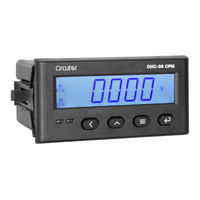
Circutor DHC-96 CPM Instruction Manual (56 pages)
DC Multimeter
Brand:
Circutor
| Category:
Measuring Instruments
| Size: 10 MB
Table of Contents
Safety Precautions
3
Disclaimer
3
Table of Contents
4
Contents
4
Revision Log
6
Symbols
6
1�- Verification Upon Reception
7
2�- Product Description
7
3�- Device Installation
8
3�1�- Prior Recommendations
8
3�2�- Installation
9
3�3�- Device Terminals
10
3�4�- Connection Diagram
11
3�4�1�- Simultaneous Voltage and Current Measurement
11
3�4�2�- Voltage Measurement
11
3�4�3�- Current Measurement Using Shunt
12
4�- Operation
13
4�1�- Display
13
4�2�- Keyboard Functions
13
4�3�- Leds
14
4�4�- Relay Outputs
14
4�5�- Analog Output
14
4�6�- Digital Inputs
14
4�7�- Display
15
4�7�1�- Maximum & Minimum Values
16
4�7�2�- Totalisers
16
5�- Configuration
17
5�1�- Configuration of the Input
19
5�1�1�- Voltage Display Value
19
5�1�2�- Voltage Measurement Range
20
5�1�3�- Current Display Value
20
5�1�4�- Current Input
21
5�1�5�- Decimal Point for Displaying Voltage
21
5�1�6�- Save Configuration
22
5�2�- Rs-485 Communications
22
5�2�1�- Modbus Address
23
5�2�2�- Baud Rate
23
5�2�3�- Data Format
24
5�2�4�- Save Configuration
24
5�3�- Analog Output
25
5�3�1�- Type of Output
25
5�3�2�- Analog Output Parameter
26
5�3�3�- Reading for the Start of the Analog Output
26
5�3�4�-Reading for the End of the Analog Output
27
5�3�5�- Save Configuration
27
5�4�- Relay Output 1
28
5�4�1�- Relay Mode
28
5�4�2�- Relay Pulse Duration
29
5�4�3�- Alarm Parameter
29
5�4�4�- Connection Delay
30
5�4�5�- Alarm Value
30
5�4�6�- Hysteresis
31
5�4�7�- Save Configuration
31
5�5�- Relay Output 2
31
5�6�- Configuration of the Display
32
5�6�1�- Login Password
33
5�6�2�- Cyclic Display
33
5�6�3�- Backlight of the Display
33
5�6�4�- Light Alarm
34
5�6�5�-Display Home Screen
34
5�6�6�- Refresh Time
35
5�6�7�- Deleting the Maximum & Minimum Values
35
5�6�8�- Deleting the Electrical Charge Totalisers
36
5�6�9�- Deleting the Energy Totalisers
36
5�6�10�- Save Configuration
36
5�7�- Software Version
37
6�- Rs-485 Communications
38
6�1�- Connections
38
6�2�- Modbus Protocol
39
6�2�1� READING EXAMPLE: FUNCTION 0X01
39
6�2�2� EXAMPLE of OPERATION of the REMOTE CONTROL: FUNCTION 0X05
39
6�3�- Modbus Commands
40
6�3�1�- Measurement Variables and Device Status
40
6�3�2�- Relay Outputs
41
6�3�3�- Digital Inputs
41
6�3�4�- REMOTE CONTROL OUTPUT (Relay Output)
42
6�3�5�- Deleting Values
42
6�3�6�- Device Configuration Variables
43
7�- Technical Features
46
8�- Maintenance and Technical Service
49
9�- Guarantee
49
10�- Ce Certificate
50
Annex A.- Configuration Menu
53
Advertisement
Related Products
Circutor DHC-96 Aac
Circutor DHC-96 mAdc
Circutor DHC-96 Adc
Circutor DHC-96 Vac
Circutor DHC-96 mVdc
Circutor DHC-96 LVdc
Circutor DHC-96 HVdc
Circutor DHC-96 Vdc
Circutor DHB-302
Circutor DHB-324
Circutor Categories
Measuring Instruments
Relays
Automobile Accessories
Battery Charger
Controller
More Circutor Manuals
Login
Sign In
OR
Sign in with Facebook
Sign in with Google
Upload manual
Upload from disk
Upload from URL