Sign In
Upload
Manuals
Brands
Cebora Manuals
Welding System
SOUND MIG 3840/T Pulse
Cebora SOUND MIG 3840/T Pulse Manuals
Manuals and User Guides for Cebora SOUND MIG 3840/T Pulse. We have
2
Cebora SOUND MIG 3840/T Pulse manuals available for free PDF download: Service Manual, Instruction Manual
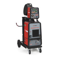
Cebora SOUND MIG 3840/T Pulse Service Manual (54 pages)
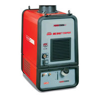
POWER SOURCE + COOLING UNIT + WIRE FEEDER
Brand:
Cebora
| Category:
Welding System
| Size: 0.96 MB
Table of Contents
Table of Contents
2
1 General Information
4
Introduction
4
General Service Policy
4
Safety Information
4
Electromagnetic Compatibility
4
2 System Description
5
Introduction
5
Technical Specifications
5
Description of SOUND MIG 3840/T Pulse System (Art. 287)
5
Description of MIG3840/T Pulse Power Source
6
Description of WF4-P Wire Feeder
8
Accessories Table
9
Description of GR54 Cooling Unit
9
3 Maintenance
10
Periodic Inspection, Cleaning
10
Welding System Fittings and Connectors
10
Control Panel Commands and Signals
11
Operating Sequences
12
Welding System Operation
12
MIG Mode
13
TIG Operation
14
MMA Mode
15
Troubleshooting
16
The Power Source Does Not Start, Control Panel off
16
Power Source Powered, Control Panel On, Fan (512) Stopped
19
System Powered, Display and Signals Do Not Show the Correct Values
20
The Start Button Produces no Effect
21
Some Signals from Connector for Accessories (BB) Do Not Work
23
System Powered, no Gas Flows from the Torch
24
System Powered, the Wire Feeder Motor Does Not Work
25
In Open Circuit Operation, the Output Voltage Is Not Regular
26
In Resistive Load Operation, the Output Voltage Is Not Regular
29
In MIG or TIG Mode, Arc Difficult to Strike, the Arc Shuts off Immediately after Striking (Stuttering Start-Up)
31
In Synergic Mode, the Welding Quality Is Not Satisfactory, the Wire Speed Is Not Suited to the Output Current
31
In MMA, Arc Difficult to Strike And/Or Unsatisfactory Welding Quality
31
In MIG Mode, When the Start Button Is Released, the Wire Sticks to the Workpiece (Ineffective Motor Braking)
32
Cooling Unit GR54 Does Not Work Correctly
33
Kit Driver + Igbt, Code 5.710.511 Replace Instructions
35
Error Codes and Alarm Signals
36
- EEPROM Error
36
- Communication Error on CAN-BUS, Detected by Control Board (543)
36
- Communication Error on the CAN-BUS between Control Panel (324) and Control Board (543)
36
10 - Missing Voltage and Current at the Power Source Output
36
13 - Missing Communication between Control Board (543) and Pre-Charge Board (562)
36
14 - Microprocessor Supply Voltage Error on Control Board (543)
37
16 - Direct Current Voltage at Pre-Charge Board (562) Output below Minimum Permitted Value
37
20 - Absence of Interlock Signal on TA Board (558)
37
25 - Error on the EPLD Bus in the Control Board (543)
37
30 - Incorrect Setting of the Minimum Current Threshold on Control Board (543)
37
41 - Connector Board (225) Missing or Disconnected
38
42 - Error in the Signal of the Motor (404) Encoder
38
43 - Communication Error with Connector Board (225)
38
52 - "Trg" on Display (O). in MIG and TIG Mode, Start Button Pressed Upon Start-Up
39
53 - "Trg" on Display (O). Start Button Pressed While Resetting from Stop Due to Temperature Outside Limits
39
54 - Short-Circuit between Torch and Workpiece Upon Start-Up
39
56 - Short-Circuit at the Output Lasts too Long
39
57 - "Mot" on Display (O). Excessive Wire Feeder Motor (404) Current
40
61 - Mains Voltage below Minimum Permitted
40
73 - "TH0" on Display (O). Led (G) Lit. Diode Group (567) High Temperature
40
74 - "TH1" on Display (O). Led (G) Lit. Igbt Group (548) High Temperature
40
75 - "H2O" on Display (O). Low Pressure in the Cooling Circuit
41
80 - "Opn" on Display (O). Wire Feed Unit Guard Open
41
99 - "OFF" on Display (O). Incorrect Mains Voltage (Machine Shutdown)
41
4 Components List
42
Power Source Art. 287 : See File Esp287.Pdf Enclosed at the End of the Manual
42
Table of Components: See File Esp287.Pdf Enclosed at the End of the Manual
42
List of Spare Parts
42
5 Electrical Diagrams
43
Power Source Art. 287 : See File Sche287.Pdf Enclosed at the End of the Manual
43
Waveforms
43
Speed Feedback Signal from the Wire Feeder Motor Encoder (404)(Par. 3.5.7)
43
Open-Circuit Voltage on the Transformer (531) Secondary Circuit (Par. 3.5.8)
43
Command Signal for Driver Boards (548) (Par. 3.5.8)
43
Output Current Feedback Signal on Resistive Load (Par. 3.5.9)
44
Wire Feeder Motor (404) Voltage During Correct Braking (Par. 3.5.13)
44
Wire Feeder Motor (404) Voltage During Incorrect Braking (Par. 3.5.13)
44
PRECHARGE" Signal (Par. 3.7.5)
44
Filter Board (542) Code 5.602.196/B
45
Pre-Charge Board (562) Code 5.602.187/A
46
Flyback Board (539) Code 5.602.184/E
47
Interface Board (543) Code 5.602.186
48
Micro Board (543) Code 5.602.185/C
49
Igbt-Driver Board (548) Code 5.602.188
50
TA Board (558) Code 5.602.123
50
Thermostat Board (551) Code 5.602.137
50
Motor Control Board (232) Code 5.602.103/B
51
Connector Board (225) Code 5.602.104/B
53
Control Panel (324) Cod. 5.602.110/C
54
Advertisement
Cebora SOUND MIG 3840/T Pulse Instruction Manual (48 pages)
Brand:
Cebora
| Category:
Portable Generator
| Size: 3.14 MB
Table of Contents
Installazione
5
Manutenzione
8
System Description
13
Installation
14
Power Source
15
Cooling Unit
16
Maintenance
17
Descripción del Sistema
22
Instalación
23
Mantenimiento
26
Beschreibung des Systems
31
Wartung
35
Advertisement
Related Products
Cebora MIG 3840/TS
Cebora MIG 3540/T
Cebora MIG 3840/T
Cebora MIG 2060/MD
Cebora MONO STAR MIG 1620/M
Cebora JAGUAR SOUND MIG 2060
Cebora TRI STAR MIG 1635/M
Cebora SOUND MIG 2035/M Pulse
Cebora MIG 5040/T
Cebora MIG 1660/M
Cebora Categories
Welding System
Portable Generator
Welding Accessories
Recording Equipment
Flashlight
More Cebora Manuals
Login
Sign In
OR
Sign in with Facebook
Sign in with Google
Upload manual
Upload from disk
Upload from URL