Sign In
Upload
Manuals
Brands
CE+T Power Manuals
Inverter
BRAVO 25
CE+T Power BRAVO 25 Parallel Inverter Manuals
Manuals and User Guides for CE+T Power BRAVO 25 Parallel Inverter. We have
1
CE+T Power BRAVO 25 Parallel Inverter manual available for free PDF download: User Manual
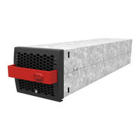
CE+T Power BRAVO 25 User Manual (71 pages)
DUAL INPUT INVERTER
Brand:
CE+T Power
| Category:
Inverter
| Size: 8.44 MB
Table of Contents
Table of Contents
2
Introduction to CE+T
6
Abbreviations
7
Warranty and Safety Conditions
8
Disclaimer
8
Technical Care
8
Installation
9
Handling
9
Surge and Transients
10
Other
10
Maintenance
10
Replacement and Dismantling
10
ECI Technology
11
On-Line Mode
12
Safe Mode
12
EPC Mode
12
MIX Mode & Walk-In Mode
12
Building Blocks
13
Inverter
13
Specifications
13
Controller - Inview S
15
Inview S - Connections
15
Inview X
16
Inview X - Connections
16
Accessories
18
Cabinet
18
Manual By-Pass
18
AC Distribution Unit
18
Miniature Circuit Breakers
18
Mccb
19
System Design
20
A la Carte
20
Installation of Bravo 25 Shelf
21
Mounting Kit for Bravo 25 Shelf
21
Electrical Installation for Bravo 25 Shelf
22
Pre Requisites
22
Bravo 25 - 230-277 Single-Phase Shelf - Terminations
23
Bravo 25 - 230-277 Three-Phase Shelf - Terminations
24
Grounding
25
DC Connection
25
AC Input Connection
25
AC Output Connection
26
Signalling
26
Remote ON/OFF
27
Internal BUS a and B
27
Shelf Rear Cover
27
Installation of Cabinet (a la Carte)
28
Unpacking the System
28
Module Packing
28
Removing the Cabinet Rear Protection
29
Hardware Connections
29
Electrical Installation
30
Positioning
30
Cabling
31
Grounding
31
Surge Suppression
31
AC Input (X2) and Output (X4)
32
DC (X1)
33
Connection Table - DC 48 VDC (X1)
33
Connection Table - DC 110 VDC (X1)
33
Connection Table - DC 380 VDC (X1)
34
Connection Table - AC Input (X2) & Output (X4)
34
Signalling
35
Operation
37
Inverter Module
37
Inview S - LCD Interface
38
LED Indications
38
Menu Structure
39
LCD Interface - Terminology
40
Inview X - LCD Interface
41
Menu Structure
46
LED Indications
47
LCD Interface - Terminology
47
Inview S and X - Web Interface
48
Login
49
Interface Areas
49
Web
51
Inserting/Removing/Replacing - Modules
53
Bravo 25 Inverter
53
Removal
53
Inserting
53
Inview S - Panel Mounting
54
Inview X - Panel Mounting
55
Fan Replacement
56
AC Output Distribution
57
Miniature Circuit Breaker Installation/Removal
57
Mccb
57
Manual By-Pass (MBP)
58
Pre-Requisites
58
MBP Auxiliary Connection
58
Manual Bypass Operation
59
MBP - Single Rotary Switch
59
MBP - Three Individual Switches
60
Finishing
61
Commissioning
62
Check List
63
Trouble Shooting and Defective Situations Fixing
64
Trouble Shooting
64
Defective Modules
65
Maintenance
66
Access Inview with Laptop
66
Manual Check
66
Optional
66
Manual By-Pass
66
Service
67
Appendix
68
Mains Connection, Single Phase
68
Mains Connection, Three Phases
69
Bravo 25 - Dimensions
70
Module
70
Shelf
70
Advertisement
Advertisement
Related Products
CE+T Power TSI BRAVO 125 VDC
CE+T Power 016-1895-10
CE+T Power 016-1898-10
CE+T Power BRAVO 10 - 48/120
CE+T Power Bravo 10 - 48/230
CE+T Power BRAVO ECI STANDARD SYSTEM 72 KVA
CE+T Power BRAVO ECI STANDARD SYSTEM 90 KVA
CE+T Power BRAVO ST-120 VAC-UL
CE+T Power e-one 10 - 48/230
CE+T Power F52A83E002431100H001
CE+T Power Categories
Inverter
UPS
Media Converter
Industrial Equipment
Power Supply
More CE+T Power Manuals
Login
Sign In
OR
Sign in with Facebook
Sign in with Google
Upload manual
Upload from disk
Upload from URL