Sign In
Upload
Manuals
Brands
Carrier TRANSICOLD Manuals
Refrigerator
PrimeLINE 69NT40-571-199
Carrier TRANSICOLD PrimeLINE 69NT40-571-199 Manuals
Manuals and User Guides for Carrier TRANSICOLD PrimeLINE 69NT40-571-199. We have
2
Carrier TRANSICOLD PrimeLINE 69NT40-571-199 manuals available for free PDF download: Operation And Service Manual
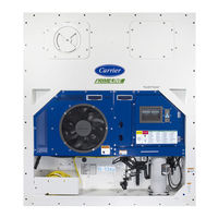
Carrier TRANSICOLD PrimeLINE 69NT40-571-199 Operation And Service Manual (186 pages)
Container Refrigeration Units
Brand:
Carrier TRANSICOLD
| Category:
Refrigerator
| Size: 6 MB
Table of Contents
Table of Contents
6
Troubleshooting
9
Figure 3.1 Refrigeration Unit - Front Section
23
Figure Number
23
Figure 3.2 Evaporator Section
24
Air-Cooled Condenser Section
25
Compressor Section
25
Figure 3.3 Compressor Section
25
Figure 3.4 Air Cooled Condenser Section
26
Figure 3.5 Brazed Plate Water-Cooled Condenser
27
Water-Cooled Condenser Section
27
Control Box Section
28
Figure 3.6 Control Box Section
28
Table Number
29
Electrical Data
29
Refrigeration System Data
29
Table 3-1 Refrigeration System Data
29
Table 3-2 Electrical Data
29
Abnormal Pressures
31
Safety and Protective Devices
31
Table 3-3 Safety and Protective Devices
31
Refrigeration Circuit
32
Standard Operation
32
Economized Operation
32
Electronic Expansion Valve (EEV)
32
Figure 3.7 Refrigeration Circuit Schematic - Standard Operation
33
Figure 3.8 Refrigeration Circuit Schematic - Economized Operation
34
Figure 3.9 Refrigeration Circuit Schematic - Water-Cooled Condenser (Brazed Plate)
35
Microprocessor
37
Temperature Control Microprocessor System
37
Control Module
37
Display Module and Keypad
37
Figure 4.1 Control Module
37
Figure 4.2 Display Module
38
Figure 4.3 Keypad
38
Table 4-1 Display Module Leds
38
Table 4-2 Keypad Function
38
Controller Software
39
Configuration Software (Cnf Variables)
39
Operational Software (CD Function Codes)
39
Modes of Operation
39
Start up - Compressor Phase Sequence
39
Start up - Compressor Bump Start
40
Perishable Mode (Temperature Control)
40
Perishable Pulldown Mode
40
Perishable Steady State Mode
40
Perishable Idle Mode (Air Circulation)
40
Perishable Heating Mode
40
Perishable Dehumidification
41
Figure 4.4 Controller Operation - Perishable Mode
41
Perishable Dehumidification - Bulb Mode
42
Perishable Economy Fan Mode
42
Perishable Mode Cooling - Sequence of Operation
43
Figure 4.5 Perishable Mode Cooling
43
Perishable Mode Heating - Sequence of Operation
44
Perishable Mode - Trim Heat
44
Frozen Mode (Temperature Control)
44
Frozen Steady State Mode
44
Figure 4.6 Perishable Mode Heating
44
Frozen Idle Mode
45
Frozen "Heat" Mode
45
Frozen Economy Mode
45
Frozen Mode Cooling - Sequence of Operation
45
Figure 4.7 Controller Operation - Frozen Mode
45
Defrost
46
Defrost Operation
46
Figure 4.8 Frozen Mode
46
Figure 4.9 Defrost
47
Defrost Related Settings
48
Protection Mode - Evaporator Fan Operation
48
Protection Mode - Failure Action
48
Protection Mode - Generator Protection
48
Protection Mode - Compressor High Temperature Protection
48
Protection Mode - Compressor Low Pressure Protection
48
Protection Mode - Perishable Mode System Pressure Regulation
48
Protection Mode - Condenser Fan Override
49
Quest
49
Controller Alarms
49
Figure 4.10 Alarm Troubleshooting Sequence
50
Pre-Trip Diagnostics
51
Datacorder
51
Table 4-3 Datacorder Function Code Assignments
52
Datacorder Configuration Software
53
Description
53
Sensor Configuration (Dcf02)
53
Table 4-4 Datacorder Configuration Variables
53
Table 4-5 Datacorder Standard Configurations
53
Logging Interval (Dcf03)
54
Alarm Configuration (Dcf07 - Dcf10)
55
Datacorder Power up
55
Sampling Type (Dcf05 & Dcf06)
55
Stored Temperature Display (Scrollback)
55
Thermistor Format (Dcf04)
55
Figure 4.11 Datacorder Configuration Screen
56
Pre-Trip Data Recording
56
USDA Cold Treatment
56
USDA Cold Treatment Procedure
56
Figure 4.12 Datacorder Probe Calibration Screen
57
Figure 4.13 Datacorder Probe Calibration Screen
57
Datacorder Communications
58
Figure 4.14 Datacorder Systems Tool Screen
58
ISO Trip Header
58
Controller Communications
59
Controller Wired Communications
59
Controller Wireless Communications
59
Figure 4.15 Dataline and Dataline Connect
59
Table 4-6 Wireless Settings Menu (Net) Options
60
Controller Configuration Variables
61
Table 4-7 Controller Configuration Variables
61
Controller Function Codes
62
Table 4-8 Controller Function Codes
62
4.10 Controller Alarm Indications
73
4.11 Controller Pre-Trip Test Codes
89
Table 4-9 Controller Pre-Trip Test Codes
89
Table 4-10 Datacorder Pre-Trip Result Records
95
Operation
97
Inspection
97
Connect Power
97
Connecting to 380/460 VAC Power
97
Connecting to 190/230 VAC Power
97
Adjust Fresh Air Makeup Vent
98
Upper Fresh Air Makeup Vent
98
Figure 5.1 Autotransformer
98
Vent Position Sensor
99
Everfresh Operation
99
Connect Water-Cooled Condenser
99
Figure 5.2 Upper Fresh Air Make up Flow Chart
99
Water-Cooled Condenser with Condenser Fan Switch
100
Water-Cooled Condenser with Water Pressure Switch
100
Starting and Stopping Instructions
100
Starting the Unit
100
Stopping the Unit
100
Start-Up Inspection
100
Physical Inspection
100
Check Controller Function Codes
100
Start Temperature Recorder in Datacorder
101
Complete Inspection
101
Pre-Trip Diagnosis
101
Starting a Pre-Trip
102
Figure 5.3 Tripwise Status in Datacorder
105
Figure 5.4 Generating Tripwise Summary Report
105
Figure 5.5 Tripwise Summary Report
106
Microprocessor Malfunction
114
6.10 no Evaporator Air Flow or Restricted Air Flow
114
6.12 Autotransformer Malfunction
114
6.14 Compressor Operating in Reverse
115
6.15 Abnormal Temperatures
115
6.16 Abnormal Currents
115
Service
117
7.1 Section Layout
117
7.2 Manifold Gauge Set
117
Figure 7.1 Manifold Gauge Set
117
Evacuating the Manifold Gauge Set
118
7.3 Service Connections
118
Figure 7.2 Manifold Gauge/Hose Set
118
7.4 Pump down the Unit
119
Figure 7.3 Service Valve
119
Automatic Pump down
120
7.5 Refrigerant Leak Checking
120
General
121
Preparation
121
Figure 7.4 Refrigeration System Service Connections
121
Evacuate and Dehydrate - Partial System
122
7.7 Refrigerant Charge
122
Checking the Refrigerant Charge
122
7.8 Converting to R-513A Refrigerant
123
7.9 Compressor
124
Removal and Replacement of Compressor
124
Figure 7.5 Compressor Kit
125
7.10 High Pressure Switch
126
Figure 7.6 High Pressure Switch Testing
126
Figure 7.7 Condenser Fan Position
129
Figure 7.8 Water-Cooled Condenser Cleaning - Forced Circulation
131
Figure 7.9 Water-Cooled Condenser Cleaning - Gravity Circulation
132
Figure 7.10 Heater Arrangement
133
Figure 7.11 Evaporator Fan Assembly
136
Figure 7.12 Access Panel Torque Pattern
137
Figure 7.13 Electronic Expansion Valve
139
Figure 7.14 Humidity Sensor
140
Figure 7.15 Access Panel Torque Sequence
140
Figure 7.16 Coil View of Economizer Solenoid Valve (ESV)
141
Figure 7.17 Economizer Expansion Valve
142
Figure 7.18 Adapter and O-Ring
143
Figure 7.19 View of Digital Unloader Valve (DUV) Assembly
144
Figure 7.20 Autotransformer
145
Table 7-1 Valve Override Control Displays for Cd41 "Selct
145
Controller Troubleshooting
146
Uploading a Software Configuration from a USB Drive
147
Downloading Datacorder Data to a USB Drive
147
Setting the Date and Time
147
Setting the Container ID
148
Removing and Installing a Controller
149
Battery Replacement
149
7.28 Temperature Sensor Service
150
Table 7-2 Sensor Resistance - AMBS, DTS, ETS, RRS, RTS, SRS, STS
152
Table 7-3 Sensor Resistance - Primeline CPDS
153
Figure 7.21 Supply Sensors - Cover Assembly and Sensors
154
Figure 7.22 Removing Front Access Panels
155
Figure 7.23 Removing Evaporator Motor
155
Figure 7.24 Return Sensors - Bracket
155
Figure 7.25 Return Sensors - Cutting Wire Ties
156
Figure 7.26 Dataline - Probe Calibration
156
Figure 7.27 Dataline - Calibrate Sensors Button
157
Figure 7.28 Dataline - Enter Service Center Information
157
Figure 7.29 Ice Bath
158
Figure 7.30 Dataline - Start Cal Button
158
Sensor Replacement
159
Figure 7.31 Dataline - Calibration Results
159
Figure 7.32 Sensor Types
160
Figure 7.33 Sensor and Cable Splice
160
Sensor RTS and RRS Reinstallation
161
Figure 7.34 Supply Sensor Positioning
161
Sensor DTS Reinstallation
162
Sensor, CPDS Reinstallation
162
Figure 7.35 Return Sensor Positioning
162
Figure 7.36 Evaporator Temperature Sensor Positioning
162
Vent Position Sensor (Vps)
163
7.30 Everfresh Service
163
Figure 7.37 Compressor Discharge Temperature Sensor
163
Table 7-4 R-134A Refrigerant Pressure Temperature Chart
164
Table 7-5 R-513A Refrigerant Pressure Temperature Chart
167
Table 7-6 Recommended Bolt Torque Values (Dry, Non-Lubricated for 18-8 Stainless Steel)
170
Figure 8.1 Legend - Standard Unit Configuration
171
Figure 8.2 Schematic Diagram
172
Figure 8.3 Unit Wiring Diagram (Sheet 1 of 2)
173
Figure 8.4 Unit Wiring Diagram (Sheet 2 of 2)
174
Eu Declaration of Conformity
177
Electrical Wiring Schematic and Diagrams
177
Wireless Certification
177
Index
181
Advertisement
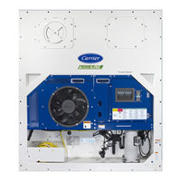
Carrier TRANSICOLD PrimeLINE 69NT40-571-199 Operation And Service Manual (194 pages)
Container Refrigeration Units
Brand:
Carrier TRANSICOLD
| Category:
Air Conditioner
| Size: 13 MB
Table of Contents
Table of Contents
3
Safety Summary
13
General Safety Notices
13
First Aid
13
Operating Precautions
13
Maintenance Precautions
13
Specific Hazard Statements
13
Introduction
17
Refrigerant
17
Configuration Identification
17
Feature Descriptions
17
Control Box
17
Temperature Readout
17
Pressure Readout
17
Compressor
17
Condenser Coil
18
Evaporator
18
Evaporator Fan Operation
18
Plate Set
18
Option Descriptions
18
Battery
18
Dehumidification
18
Usda
18
Autotransformer
18
Handles
18
Volt Cable
19
Cable Restraint
19
Upper Fresh Air Makeup
19
Labels
19
Controller
19
Condenser Grille
19
Everfresh
19
Quest
19
Tripwise
20
Fuelwise
20
Description
21
General Description
21
Refrigeration Unit - Front Section
21
Figure 3.1 Refrigeration Unit - Front Section
21
Compressor Section
22
Figure 3.3 Compressor Section
22
Air-Cooled Condenser Section
23
Figure 3.4 Condenser Fan
23
Figure 3.5 Condenser Section for Pids < NT3100 (Steel Receiver)
23
Figure 3.6 Condenser Section for Pids > NT3100 (Aluminum Receiver)
24
Water-Cooled Condenser Section
25
Fresh Air Makeup Vent
25
Figure 3.7 Brazed Plate Water-Cooled Condenser
25
Figure 3.8 Fresh Air Vent
25
Evaporator Section
26
Figure 3.9 Evaporator Section
26
Control Box Section
27
Figure 3.10 Control Box Section
27
Refrigeration System Data
28
Electrical Data
28
Table 3-1 Refrigeration System Data
28
Table 3-2 Electrical Data
28
Safety and Protective Devices
30
Table 3-3 Safety and Protective Devices
30
Refrigeration Circuit
31
Standard Operation
31
Economized Operation
31
Electronic Expansion Valve (EEV)
31
Figure 3.11 Refrigeration Circuit Diagram - Standard Operation
32
Figure 3.12 Refrigeration Circuit Diagram - Economized Operation
33
Figure 3.13 Refrigeration Circuit Diagram - Water-Cooled Condenser
34
Microprocessor
35
Temperature Control Microprocessor System
35
Controller
35
Figure 4.1 Controller, Micro-Link 5
35
Display Module and Keypad
36
Figure 4.2 Display Module and Keypad
36
Table 4-1 Display Module Indicator Lights
36
Controller Software
37
Table 4-2 Keypad Function
37
Configuration Software (Cnf Variables)
38
Operational Software (CD Function Codes)
38
Table 4-3 Controller Function Codes (CD) - Summary
39
Table 4-4 Controller Function Codes (CD) - Descriptions
40
Modes of Operation
53
Start up
53
Perishable Mode Temperature Control
53
Figure 4.3 Perishable Mode - Cooling and Heating Chart
54
Figure 4.4 Perishable Mode Cooling Schematic
55
Perishable Mode - Modes and Options
56
Figure 4.5 Perishable Mode Heating Schematic
56
Frozen Mode Temperature Control
59
Figure 4.6 Frozen Mode - Cooling and Heating Chart
59
Frozen Mode - Modes and Options
60
Figure 4.7 Frozen Mode Schematic
60
Defrost
61
Defrost Operation
61
Defrost Related Settings
62
Protection Modes of Operation
62
Figure 4.8 Defrost Schematic
62
Controller Alarms
63
Table 4-5 Alarm Indications - Summary
65
Table 4-6 Alarm Indications - Descriptions
66
Auto Mode and Manual Mode
80
Pre-Trip Inspection Initiation
80
Pre-Trip Inspection Termination
81
Controller Pre-Trip Test Codes
81
Table 4-7 Controller Pre-Trip Test Codes
81
Controller Communications
87
Micro USB Port Connection
87
Figure 4.9 Connections to the Controller
87
Wireless Connection
88
Figure 4.10 Containerlink - Downloads
88
Figure 4.11 Containerlink - View Real Time Data
89
Optional Interrrogator Ports Connection
94
Datacorder
94
Datacorder Description
94
Datacorder Configuration Software
94
Table 4-8 Datacorder Configuration Variables
95
Table 4-9 Datacorder Sensor Configurations
95
Datacorder Operational Software
97
Table 4-10 Datacorder Function Code Assignments
97
Datacorder Power up
98
Datacorder Communications
99
Pre-Trip Data Recording
99
Table 4-11 Datacorder Pre-Trip Result Records
99
Operation
101
Inspecting the Unit
101
Connecting Power
101
Connecting to 380/460 VAC Power
101
Connecting to 190/230 VAC Power
101
Adjusting Fresh Air Makeup Vent
102
Upper Fresh Air Makeup Vent
102
Figure 5.1 Autotransformer
102
Vent Position Sensor
103
Connecting Water-Cooled Condenser
103
Water-Cooled Condenser with Water Pressure Switch
103
Figure 5.2 Upper Fresh Air Make up Flow Chart
103
Starting and Stopping Instructions
104
Starting the Unit
104
Stopping the Unit
104
Start-Up Inspection
104
Performing a Pre-Trip
105
Starting a Pre-Trip from the Keypad
105
Displaying Pre-Trip Test Results from the Keypad
106
Probe Diagnostics
106
Enabling Operating Modes
107
QUEST Mode
107
Fuelwise Mode
107
Tripwise Mode
107
Automatic Cold Treatment (ACT) Mode
108
Automatic Setpoint Change (ASC) Mode
109
Pharma Mode
110
Everfresh Mode
110
Troubleshooting
113
Figure 6.1 Unit Troubleshooting Sequence
113
Unit will Not Start or Starts then Stops
114
Unit Operates Long or Continuously in Cooling
114
Table 6-1 Troubleshooting Symptoms
114
Unit Runs but Has Insufficient Cooling
115
Unit will Not Heat or Has Insufficient Heating
115
Unit will Not Terminate Heating
115
Unit will Not Defrost Properly
115
Abnormal Pressures
115
Figure 3.2 Compressor
116
Microprocessor Malfunction
117
Evaporator Air Flow or Restricted Air Flow
117
Electronic Expansion Valve Malfunction
117
Autotransformer Malfunction
117
Water-Cooled Condenser or Water Pressure Switch
118
Compressor Operating in Reverse
118
Abnormal Temperatures
118
Abnormal Currents
118
Service
119
Section Layout
119
Manifold Gauge Set
119
Figure 7.1 Manifold Gauge Set
119
Evacuating the Manifold Gauge Set
120
Service Connections
120
Figure 7.2 Manifold Gauge / Hose Set
120
Connecting the Manifold Gauge Set
121
Removing the Manifold Gauge Set
121
Pump down the Unit
121
Figure 7.3 Service Valve
121
Automatic Pump down
122
Figure 7.4 Refrigeration System Service Connections
123
Figure 7.5 Compressor Kit
127
Figure 7.6 High Pressure Switch Testing with Nitrogen
128
Figure 7.7 Condenser Fan Position
131
Figure 7.8 Water-Cooled Condenser Cleaning - Forced Circulation
133
Figure 7.9 Water-Cooled Condenser Cleaning - Gravity Circulation
134
Figure 7.10 Heater Arrangement
135
Figure 7.11 Evaporator Fan Assembly
137
Figure 7.12 Access Panel Torque Pattern
138
Figure 7.13 Electronic Expansion Valve (EEV)
140
Figure 7.14 Economizer Solenoid Valve (ESV)
141
Figure 7.15 Economizer Solenoid Valve (ESV) Coil Assembly
142
Figure 7.16 Economizer Expansion Valve (EXV)
142
Figure 7.17 Adapter and O-Ring
143
Figure 7.18 Digital Unloader Valve (DUV) Assembly
145
Figure 7.19 Autotransformer
146
Table 7-1 Valve Override Control Displays for Cd41 "Selct
146
Figure 7.20 Controller Harness Tool
155
Figure 7.21 Sensor Types
161
Figure 7.22 Sensor and Cable Splice
162
Figure 7.25 Evaporator Temperature Sensor Positioning
164
Figure 7.26 Compressor Discharge Temperature Sensor (CPDS)
164
Table 7-2 Sensor Resistance - AMBS, DTS, ETS, RRS, RTS, SRS, STS
165
Table 7-3 Sensor Resistance - Primeline CPDS
166
Figure 7.27 Humidity Sensor
167
Table 7-4 R-134A Refrigerant Pressure Temperature Chart
170
Table 7-5 R-513A Refrigerant Pressure Temperature Chart
173
Table 7-6 Recommended Bolt Torque Values (Dry, Non-Lubricated for 18-8 Stainless Steel)
176
Advertisement
Related Products
Carrier TRANSICOLD PrimeLINE 69NT40-571-001
Carrier TRANSICOLD PrimeLINE ONE 69NT40-575-001
Carrier TRANSICOLD PrimeLINE ONE 69NT40-575-199
Carrier TRANSICOLD 69NT40-511-200
Carrier TRANSICOLD 69NT40-511-299
Carrier TRANSICOLD 69NT40-489
Carrier TRANSICOLD 69NT40-541-200
Carrier TRANSICOLD 69NT40-541-299
Carrier TRANSICOLD PrimeLINE 69NT40-571
Carrier TRANSICOLD PrimeLINE 69NT40-571-100
Carrier TRANSICOLD Categories
Refrigerator
Automobile Accessories
Portable Generator
Air Conditioner
Engine
More Carrier TRANSICOLD Manuals
Login
Sign In
OR
Sign in with Facebook
Sign in with Google
Upload manual
Upload from disk
Upload from URL