Sign In
Upload
Manuals
Brands
Carrier Manuals
Air Conditioner
EM-17
Carrier EM-17 Manuals
Manuals and User Guides for Carrier EM-17. We have
1
Carrier EM-17 manual available for free PDF download: Operation And Service
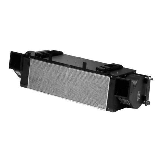
Carrier EM-17 Operation And Service (42 pages)
Large Split Systems
Brand:
Carrier
| Category:
Air Conditioner
| Size: 0.87 MB
Table of Contents
Table of Contents
3
Safety Summary
6
Safety--1
6
Description
8
Introduction
8
Evaporator Section (EM--17)
8
Condensing Section
8
Compressor Assembly
8
Figure 1--1 Coach Cutaway View
9
Table 1--1 Model
9
Table 1--2 Additional Support Manuals
9
System Operating Controls and Components
10
Panel Assembly, Control Box
10
Figure 1--2 Panel Assembly, Control Box
10
Refrigerant System Component Specifications
11
Figure 1--3 Relay Board
11
Safety Devices
12
Electrical Specifications -- Evaporator (Em--17) Motor
12
ELECTRICAL SPECIFICATIONS -- Condenser (CM--5) Fan Motors
12
Electrical Specifications Sensors
12
Table 1--4 Safety Devices
12
Safety Devices
13
Air Conditioning Refrigeration Cycle
13
Figure 1--4 Refrigerant Flow Diageam (DC12175)
14
Figure 1--5 Refrigerant Flow Diagram DC12174
15
Operation
16
Starting Andstopping Instructions
16
Starting
16
Stopping
16
Pre--Trip--Inspection
16
Unit Operation
16
Temperature Control
16
Cooling Mode
16
Vent Mode
16
Compressor Unloader Control
16
Condenser Fan Control
17
Compressor Clutch Control
17
Liquid Line Solenoid Control
17
Sequence of Operation
17
Troubleshooting
19
System will Not Cool
19
System Runs but Has Insufficient Cooling
19
Abnormal Pressures
19
Figure 4--14 Compressor
19
Table 3-1 General System Troubleshooting Procedures
19
Abnormal Noise or Vibrations
20
Control System Malfunction
20
No Evaporator Air Flow or Restricted Air Flow
20
Expansion Valve Malfunction
20
Heating Malfunction
20
Service
21
Maintenance Schedule
21
Suction and Discharge Service Valves
21
Installing Manifold Gauge Set
22
Figure 4--1 Suction or Discharge Service Valve
22
System Pump down for Low Side Repair
23
Figure 4--3 Manifold Gauge Set (R-134A)
23
Refrigerant Removal from an Inoperative Compressor
24
Figure 4--4 Low Side Pump down Connections
24
Figure 4--5 Compressor Service Connections
24
Removing Entire System Charge
25
Refrigerant Leak Check
25
Evacuation and Dehydration
25
General
25
Procedure for Evacuation and Dehydrating System (Triple Evacuation)
25
Figure 4--6 System Charge Removal Connections
25
Procedure for Evacuation and Dehydrating System (One Time Evacuation)
26
Figure 4--7 Vacuum Pump Connections
26
Adding Refrigerant to System
27
Adding Full Charge
27
Adding Partial Charge
27
Checking for Noncondensibles
27
Checking and Replacing High or Low Pressure Switch
27
Figure
27
Figure 4--8 Checking High Pressure Switch
28
Figure 4--9 Condenser Cover Removal
28
Figure 4--10 Filter-Drier Removal
28
Figure 4--11 Liquid Line Solenoid Valve
29
Figure 4--12 Thermostatic Expansion Valve
30
Figure 4--13 Thermostatic Expansion Valve Bulb and Thermocouple
30
Table
30
Figure 4--15 Removing Bypass Piston Plug
31
Figure 4--16 Compressor Clutch
32
Table 4--1 Temperature Sensor Resistance
33
Figure 4-10. Electric Unloader Schematic
34
Table 4--2 R-134A Temperature - Pressure Chart
35
Figure 5--1 Electrical Control Panel Relay Board (RB) & Electronic Thermostat (TH) Outline Views
36
Figure 5--2 Schematic
37
Advertisement
Advertisement
Related Products
Carrier Estrella Premium
Carrier ESTRELLA
Carrier EEZ 38MVC
Carrier EnergyX 48HC
Carrier EnergyX 50HC
CARRIER Edge TP-PRH
Carrier ECMCT8-4
Carrier ERVCCSHA1100
Carrier Performance Edger Thermidistat Control TP-NRH01-B
Carrier EHK3-08B
Carrier Categories
Air Conditioner
Heat Pump
Furnace
Thermostat
Chiller
More Carrier Manuals
Login
Sign In
OR
Sign in with Facebook
Sign in with Google
Upload manual
Upload from disk
Upload from URL