Sign In
Upload
Manuals
Brands
Carrier Manuals
Chiller
AquaForce 30XBP 450
Carrier AquaForce 30XBP 450 Manuals
Manuals and User Guides for Carrier AquaForce 30XBP 450. We have
1
Carrier AquaForce 30XBP 450 manual available for free PDF download: Installation, Operation And Maintenance Instructions
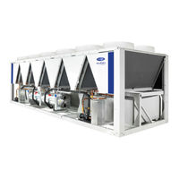
Carrier AquaForce 30XBP 450 Installation, Operation And Maintenance Instructions (88 pages)
Air-Cooled Screw Chillers
Brand:
Carrier
| Category:
Chiller
| Size: 6.58 MB
Table of Contents
Table of Contents
3
1 Introduction
5
Installation Safety Considerations
5
Equipment and Components under Pressure
6
Maintenance Safety Considerations
6
Repair Safety Considerations
7
2 Preliminary Checks
9
Check Equipment Received
9
Moving and Siting the Unit
9
3 Dimensions, Clearances
11
30XB 250 to 350, 30XBE 250 to 350, 30XBP 250 to 350, 30XB 250 to 200 with Option 254/255
11
30XB 400 to 500, 30XBE 400 to 500, 30XBP 400 to 450, 30XB 350 to 400 with Option 254/255
11
30XBP 500, 30XB 500 with Options 254/255, 50 (Heat Recovery) or 118A (Free Cooling), 30XBE 500 with Options 50 or 118A
12
30XB 600 to 900, 30XBE 600 to 850, 30XBP 600 to 800, 30XB 600 to 700 with Option 254/255
12
119 (High Efficiency), 30XBE 850 Option 50 or 118A
13
30XBE1000, 30XBP1000, 30XB-900 Option 254/255, 30XB-1000 Option 50 or 118A or 119
13
30Xb-1200
14
30XB-1100 to 1400, 30XBP-1100 to 1400
14
30Xb 1500, 30Xbe 1500, 30Xbp 1500
15
30XB 1550 Module 1/2
15
30XB-1550 Module 2/2
16
30XB 1700, 30XBE 1700 - Module 1/2
16
30XB 1700, 30XBE 1700 - Module 2/2
17
Multiple Chiller Installation
17
Distance to the Wall
17
Underneath a Roof
17
4 Physical and Electrical Data for 30Xb Units
18
Physical Data 30XB
18
Physical Data 30XBE
22
Physical Data 30XBP
26
Physical Data 30XB with Option 254 or 255
30
Short-Circuit Stability Current for All Units
33
Electrical Data
34
Compressor Electrical Data
45
Compressor Usage Per Circuit (A, B, C, D)
46
Electrical Data, Optional Hydraulic Module
47
5 Electrical Connection
49
Power Supply
49
Voltage Phase Imbalance (%)
49
Power Connection/Disconnect Switch
49
Recommended Wire Sections
49
Power Cable Entry
49
Field Control Wiring
50
6 Application Data
51
Operating Range
51
Minimum Chilled Water Flow (Units Without Hydraulic Module)
51
Maximum Chilled (Units Without Hydraulic Module)
51
Variable Flow Evaporator
51
System Minimum Water Volume
52
Maximum System Water Volume
52
Evaporator Water Flow Rate
52
Evaporator Pressure Drop Curve
53
7 Water Connections
54
Operating Precautions
54
Victaulic Water Connections
55
Flow Control
56
Evaporator Water Box Bolt Tightening
56
Frost Protection
56
Operation of Two Units in Master/Slave Mode (Option 58)
56
Pump Characteristics
57
8 Free-Cooling Option (Option 118A)
59
Physical Data, 30XB Units with Free-Cooling Option (Option 118A)
59
Operating Limits
59
Operation
59
9 Heat Reclaim Condenser Option (Option 50)
60
Physical Data, 30XB Units with Heat Reclaim Condenser Option
60
Dimensions, Clearances
60
Condenser Location
66
Condenser Water Connections
66
Operating Limits for Stable Operation (no Mode Changeover)
66
Operating Limits for Changeover between Modes
67
Flow Control
67
Heat Reclaim Operation
67
Condenser Pump Selection
67
Frost Protection
68
10 Fans with Available Pressure (Option 10)
68
11 Unit Operation with a Free Cooling Drycooler (Option_313)
69
Unit Operation with a Free Cooling Drycooler (Optional)
69
12 Major System Components and Operation Data
70
Direct-Drive Twin-Screw Compressor with Variable Capacity Slide Valve
70
Pressure Vessels
70
High Pressure Safety Loop (SRMCR)
71
Condensers
72
Fans
72
Electronic Expansion Valve (EXV)
73
Moisture Indicator
73
Filter Drier
73
Sensors
73
Service Valve (Option 92)
73
Power Factor Correction Capacitors (Option 231)
73
13 Main Options
75
14 Standard Maintenance
78
Level 1 Maintenance
78
Level 2 Maintenance
78
Level 3 (or Higher) Maintenance
78
Tightening Torques for the Main Electrical Connections
79
Tightening Torques for the Main Bolts and Screws
79
Condenser Coil
80
Evaporator Maintenance
80
Compressor Maintenance
80
Precaution for Compressor Power Supply Bus Bar Connection
81
Check of Power Factor Correction Capacitors
81
15 Final Shutdown
82
Shutting down
82
Recommendations for Disassembly
82
Fluids to be Recovered for Treatment
82
Materials to be Recovered for Recycling
82
Waste Electrical and Electronic Equipment (WEEE)
82
16 Start-Up Checklist for 30Xb Liquid Chillers (Use for Job File)
83
17 Annexes (Attached to the Instruction Manual Kit)
85
Annex 1: Conformity Declaration
85
Annex 2: Electrical Diagram
85
Annex 3: PID
85
Annex 4: Dimensional Drawings
85
Advertisement
Advertisement
Related Products
Carrier AquaForce 30XBP 400
Carrier AquaForce 30XBP series
Carrier AquaForce 30XBP 300
Carrier AquaForce 30XBP 350
Carrier AquaForce 30XBP 500
Carrier AquaForce 30XBP 750
Carrier AquaForce 30XBP 800
Carrier AquaForce 30XBP 900
Carrier AquaForce 30XBP 1000
Carrier AquaForce 30XBP 1100
Carrier Categories
Air Conditioner
Heat Pump
Furnace
Thermostat
Chiller
More Carrier Manuals
Login
Sign In
OR
Sign in with Facebook
Sign in with Google
Upload manual
Upload from disk
Upload from URL