Sign In
Upload
Manuals
Brands
Carrier Manuals
Furnace
59SC2D
Carrier 59SC2D Manuals
Manuals and User Guides for Carrier 59SC2D. We have
1
Carrier 59SC2D manual available for free PDF download: Installation, Start-Up, Operating And Service And Maintenance Instructions
Carrier 59SC2D Installation, Start-Up, Operating And Service And Maintenance Instructions (75 pages)
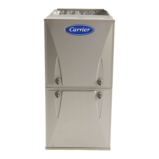
Single Stage, 35-in. (889 mm) Tall 4-Way Multipoise Condensing Gas Furnace
Brand:
Carrier
| Category:
Furnace
| Size: 8.99 MB
Table of Contents
Table of Contents
1
Important Information
2
Dimensional Drawing
3
Safety Information
4
Safety Considerations
4
Freeze Protection and Return Air Temperature
5
Multipoise Orientations
5
Minimum Clearances to Combustible Materials
5
General Installation
6
Gas Piping and Gas Pipe Pressure Testing
6
Electrical Connections
6
Codes and Standards
6
Loose Parts Bag
6
Electrostatic Discharge (ESD) Precautions Procedure
7
Location
7
Ventilated Combustion Air Applications
8
Air for Combustion and Ventilation
8
Minimum Free Area Required
9
Minimum Space Volumes
9
Outdoor Combustion Air Method
10
Combination of Indoor and Outdoor Air
10
Condensate Trap
11
Example of Field Drain Attachment
12
To Relocate the Condensate Trap
12
Condensate Drain Connection
14
Knockout Removal
14
For Left Side Condensate Drain Connection
15
Drain Trap Connection and Routing
15
Modify Rubber Drain Elbow
15
Upflow Installation
16
N Coil Installation
16
Supply Air Connections
16
Return Air Connections
16
Downflow Installation
17
Upflow/Downflow Return Air Configurations and Restrictions
17
Filter Arrangement
19
Opening Dimensions
19
Installation on Combustible Flooring
19
Filter and Return Duct Sizing
20
Filter Media Pressure Drop (Clean) Versus Airflow
20
Filter Media Pressure Drop (Clean) Versus Face Velocity
21
Air Filter Selection and Duct Sizing
21
Air Filter Located in Filter Cabinet
21
Optional Media Cabinet Accessory
22
Working Platform for Attic Installation
23
Suspended Furnace Installation
23
Ductwork Acoustical Treatment
24
Platform Furnace Support/Suspended Furnace Support
24
Location Relative to Cooling Equipment
24
Air Ducts
24
Air Delivery - CFM (with Filter)
25
Pressure Testing
26
Gas Piping
26
Maximum Capacity of Pipe
26
Gas Pipe Grommet
27
115 - V Wiring
27
Electrical Connections
27
Typical Single-Stage Wiring Diagram
28
Electrical Data
28
J-Box Installation
29
External Electrical Box on Furnace Casing
29
24-V Wiring
30
Alternate Power Supplies
30
BX Cable Installation in Furnace J-Box
30
Power Cord Installation in Furnace J-Box
30
Example of Single Stage Furnace Control
31
Venting
32
Thermostat Wiring Diagrams
32
Ventilated Combustion Air Systems
34
Venting Systems
34
Non-Direct Vent (1-Pipe) System
34
Direct Vent / 2-Pipe System
34
Vent Termination Kit for Direct Vent (2- -Pipe) System
35
Locating the Vent Termination
36
Direct Vent Termination Clearance
37
Ventilated Combustion Air and Non-Direct Vent Termination Clearance
38
Inside Corner Terminations
39
Size the Vent and Combustion Air Pipes
40
Ventilated Combustion Air
40
Non-Direct Vent / 1-Pipe System
40
Recommended Combustion Air Inlet Moisture Trap
42
Deductions from Maximum Equivalent Vent Length
44
Maximum Equivalent Vent Length
44
Inducer Vent Elbow
45
Combustion Air and Vent Piping Insulation
45
Near Furnace Vent Connections
45
Configure the Furnace
45
Notes for Venting Options
47
Maximum Allowable Exposed Vent Lengths in Unconditioned Space Table
48
Install the Vent and Combustion Air Pipes
49
Installing the Vent Pipe Adapter and Combustion Air Pipe Adapter
49
Hanger Spacing
50
Optional Installation of the Vent Pipe
50
Optional Vent Pipe Flush with Adaptor
50
Polypropylene Fittings
51
Installing the Vent Termination
51
Inducer Outlet Restrictor
52
Venting System Length Calculations
53
Prime Condensate Trap with Water
54
Purge Gas Lines
54
Start- -Up, Adjustment, and Safety Check
54
Adjustments
55
Altitude Derate Multiplier for U.S.A
55
Adjust Manifold Pressure
56
Check Inlet Gas Pressure
56
Adjust Temperature Rise
57
Adjust Blower off Delay (Heat Mode)
57
Adjust Cooling Airflow
57
Adjust Thermostat Heat Anticipator
58
Check Safety Controls
58
Orifice Size and Manifold Pressure (In. W.C.) for Gas Input Rate
59
Service Label Information
61
Electrical Controls and Wiring
62
Service and Maintenance Procedures
62
Gas Rate
62
Retrieving Stored Fault Codes
63
Component Self-Test
63
Blower Motor and Wheel Maintenance
64
Cleaning And/Or Replacing Air Filter
64
Cleaning Burners and Flame Sensor
66
Servicing Hot Surface Ignitor
66
To Reinstall Burner Assembly
66
Flushing Collector Box and Drainage System
67
Cleaning Condensate Drain and Trap
67
To Re-Install Condensate Drain and Trap
67
Checking Heat Pad Operation
68
Cleaning Heat Exchangers
68
Winterization
69
Troubleshooting
70
Sequence of Operation
72
Connection Diagram
73
Schematic Diagram
73
Parts Replacement Information Guide
74
Advertisement
Advertisement
Related Products
Carrier 59SC2A
Carrier 59SC2B
Carrier 59SC2A100S21-14
Carrier 59SC2C040-10
Carrier 59SC2C100-20
Carrier 59SC2C120-20
Carrier 59SC2E
Carrier 59SC2C100-16
Carrier 59SC2C080-20
Carrier 59SC2C080-16
Carrier Categories
Air Conditioner
Heat Pump
Furnace
Thermostat
Chiller
More Carrier Manuals
Login
Sign In
OR
Sign in with Facebook
Sign in with Google
Upload manual
Upload from disk
Upload from URL