Sign In
Upload
Manuals
Brands
Capstone Manuals
Controller
Microturbine C600S
Capstone Microturbine C600S Manuals
Manuals and User Guides for Capstone Microturbine C600S. We have
1
Capstone Microturbine C600S manual available for free PDF download: Installation Manual
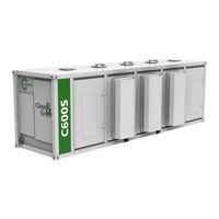
Capstone Microturbine C600S Installation Manual (122 pages)
Brand:
Capstone
| Category:
Controller
| Size: 5 MB
Table of Contents
Table of Contents
3
1 Introduction
8
Safety Information
8
Symbols
9
General Precautions
10
Electrical Precautions
11
Fuel Precautions
12
Referenced Documents
13
Table 1. Referenced Documents
13
Disclaimer
14
C1000S/C800S/C600S Models
14
Figure 1. C1000S/C800S/C600S Models
15
Figure 2. C800S and C600S Models in Five Bay Enclosure
16
2 Microturbine Handling
17
Receiving and Inspection
17
Damage Reporting
17
Loose-Shipped Items
17
Storage
18
Basic Storage Requirements (up to 6 Months)
18
Extended Storage Requirements (Longer than 6 Months)
18
Non-Operation
19
Figure 3. Locking the Battery Isolation Switch
19
Rigging
20
Figure 4. C1000S/C800S/C600S Lifting Example
21
Assembly
22
3 Site Considerations
23
Climatic Conditions
23
Coastal and Humid Environments
23
Arid/Dusty Climates
23
Temperature Extremes
24
High Altitudes
24
Compliance, Standards and Codes
25
Microturbine Certifications
25
Grid Interconnection Planning
26
4 Customer Connections
29
Figure 5. C1000S/C800S/C600S Connections
29
Fuel Connection
30
Figure 6. Gaseous Fuel Connection
30
Table 2. Gaseous Fuel Connection Specifications
30
Exhaust Connection
31
Exhaust Specifications
31
Figure 7. Liquid Fuel Connection
31
Table 3. Liquid Fuel Connection Specifications
31
Rain Cap Removal
32
Electrical Connections
32
Electrical Conduit Installation
32
Figure 8. Exhaust Outlet Assembly
32
Figure 9. Cable Access Locations
33
High Power Connections
34
Figure 10. High Power Bus Bar Lugs
34
Table 4. N - L1 - L2 - L3 Lug Specifications
34
Table 5. Ground Bar Specifications
34
Heater Power Connections
35
Table 6. Power Cable Sets
35
Table 7. Heater Power Connections
35
Figure 11. Heater Power Connections
36
Controller Customer Connections
37
Figure 12. C1000 Series Controller Connections
37
Figure 13. C1000 Series Controller Terminal Blocks for External Connections
38
Table 8. Terminal Block Wire Specifications
38
5 Mechanical Installation
39
Mounting
40
Foundation
40
Table 9. Microturbine Component Weights
40
Mounting the Microturbine
41
Figure 14. C1000S/C800S/C600S Frame Contact Locations (Bottom View)
41
Orientation
42
Figure 15. Microturbine Orientation Example #1
42
Service Clearances
43
Figure 16. Microturbine Orientation Example #2
43
Figure 17. Microturbine Orientation Example #3
43
Figure 18. C1000S/C800S/C600S Installation Clearances - Side View
44
Figure 19. C1000S/C800S/C600S Installation Clearances - Top View
45
Ventilation
46
Figure 20. Example Site Path for Engine and Component Delivery
46
Ventilation Recommendations
47
Figure 21. Airflow Paths for a C1000S/C800S/C600S Microturbine
48
Figure 22. Orientation to Prevailing Winds
49
Air Inlet
50
Enclosure/Electronics Exhaust
50
Engine Exhaust
50
Table 10. Air Flow Requirements at ISO Conditions with Zero Backpressure
50
Table 11. Heat Rejection Per Microturbine Model
50
Common Exhaust Ducting
52
Figure 23. Ducting Installation Example
53
Figure 24. Backflow Valve Requirements
54
6 Fuel Delivery (Pipeline Natural Gas)
56
Fuel Conditioning System
56
Figure 25. Pipeline Natural Gas Installation Examples
57
Compressor Filter
58
Condensate Drain
58
Microturbine Filter
58
Sediment Trap
58
Shutoff Valve
58
Third Party Compressor
58
Flame Arrestor (Optional)
59
Inlet Pressure Indicator
59
Microturbine Inlet Pressure Regulator
59
Pressure Relief Valve
59
Purge Line
59
Raw Natural Gas
60
Biogas
60
Liquefied Petroleum Gas (LPG)
60
General Considerations for Gaseous Fuels
60
Pressure
60
Dew Point Suppression
61
Condensate Removal
61
Low Temperature Concerns
62
Hydrogen Sulfide (H S)
62
Heat Tracing
63
Piping
63
Materials Selection
64
Instrumentation and Controls
64
Black Start/Dual Mode Considerations
65
Liquid Fuel
65
7 Electrical Installation
66
General Requirements
66
Electrical Connections Considerations
66
Phase Sequence
67
Grounding Requirements
67
Protective Earth (PE) / Chassis Ground
67
Grounding the Microturbine Neutral
68
Figure 26. Microturbine Neutral-To-Ground Connection
69
Overcurrent Protection and Disconnecting Devices
70
Table 12. Overcurrent Protection Sizing
70
Figure 27. Recommended Device Layout - Grid Connect
71
CE Disconnect Requirements
72
Figure 28. Recommended Device Layout - Stand Alone
72
Transformer Requirements
73
Transformer Applications
73
Transformer Sizing
73
Table 13. Recommended Transformer Sizes (Per System)
73
Grid Connect Input Impedance Calculation
74
Figure 29. Typical Transformer Installation with Impedance Percentages - 480 V
75
Figure 30. Typical Transformer Installation with Impedance Percentages - 400 V
76
Transformer Benefits for 480/400 V Operation in Grid Connect
77
Transformers for Stand Alone
77
Grid Connect Mode
78
Grid Connections
78
Table 14. Grid Connect Allowable Configurations Matrix
78
Figure 31. Wye Service with 3-Pole Breaker
80
Figure 32. Wye Service with 4-Pole Breaker
81
Figure 33. Wye Service with Wye/Wye Isolation Transformer and 3-Pole Breaker
82
Figure 34. Wye Service with Wye/Wye Isolation Transformer and 4-Pole Breaker
83
Figure 35. Delta Service with Delta/Wye Isolation Transformer and 3-Pole Breaker
84
Figure 36. Delta Service with Delta/Wye Isolation Transformer and 4-Pole Disconnect
85
Figure 37. Delta Service with Grounding Transformer and 3-Pole Breaker
86
Figure 38. Delta Service with Grounding Transformer and 4-Pole Breaker
87
Figure 39. One to Three Microturbines
88
Figure 40. Four Microturbines
89
Standalone Mode
90
Overview
90
Figure 41. Five Microturbines
90
Stand Alone Cyclic Loads
91
Stand Alone Connections
91
Figure 42. Stand Alone Load Configuration
92
Figure 43. Delta/Delta Isolation Transformer
93
Figure 44. Delta/Wye Isolation Transformer
94
Figure 45. Wye/Delta Isolation Transformer
95
Figure 46. Wye/Wye Isolation Transformer
96
Figure 47. One to Three Microturbines
97
Figure 48. Four Microturbines
98
Figure 49. Five Microturbines
99
Dual Mode
100
Dual Mode Connections
100
Figure 50. Wye Service with 3-Pole Breaker
101
Figure 51. Delta Service with Delta/Wye Isolation Transformer and 3-Pole Breaker
102
Figure 52. Wye Service with 4-Pole Breaker
103
Figure 53. Delta Service with Delta/Wye Isolation Transformer and 4-Pole Disconnect
104
Harmonics
105
Measuring Harmonics
105
Mitigating Harmonics
106
8 Communication
108
Ethernet Communication
108
Figure 54. Communication and Control Overview
108
C1000 Series Controller TB1 Connections
109
Emergency Stop
109
Multiple Microturbine (RS485) Connections
111
Figure 55. E-Stop Connections
111
Table 15. External RS485 Connections at TB1
112
Figure 56. Multiple Microturbine (RS-485) Connections
113
Battery Wakeup Connections
114
Modbus
114
Figure 57. Battery Wakeup Connection
114
Figure 58. Modbus Connections
114
Figure 59. Typical Power Meter Installation
115
C1000 Series Controller TB3 Connections
116
Remote Start/Stop
116
Dmsc
116
Figure 60. Typical Remote Start/Stop Connection
116
Fault Inputs
117
Figure 61. DMSC Terminal Block Connections
117
Figure 62. Fault Input Connections
117
Fault Input
118
External Controller Connections
118
Dual Mode Connections to a CLC
119
Figure 63. Digital Communications Connections for Dual Mode CLC and Two C1000S
120
Figure 64. Example Connections from a Dual Mode CLC to a C1000
121
Grid Connect C1000 Connections to a CLC
122
Advertisement
Advertisement
Related Products
Capstone Microturbine C1000 Series
Capstone Microturbine C1000S
Capstone Microturbine C800S
Capstone MicroTurbine C65
Capstone CS-6000
Capstone Categories
Controller
Lighting Equipment
Indoor Furnishing
Bicycle Accessories
Automobile Accessories
More Capstone Manuals
Login
Sign In
OR
Sign in with Facebook
Sign in with Google
Upload manual
Upload from disk
Upload from URL