Sign In
Upload
Manuals
Brands
Canon Manuals
Office Equipment
Finisher-W1 PRO
Canon Finisher-W1 PRO Manuals
Manuals and User Guides for Canon Finisher-W1 PRO. We have
1
Canon Finisher-W1 PRO manual available for free PDF download: Service Manual
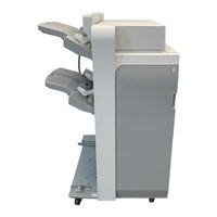
Canon Finisher-W1 PRO Service Manual (376 pages)
Brand:
Canon
| Category:
Office Equipment
| Size: 28 MB
Table of Contents
Table of Contents
4
Safety Precautions
10
Points to Note before Servicing
11
Points to Note at Cleaning
11
Notes on Assembly/Disassembly
11
Product Overview
12
Product Specifications
13
Finisher
13
Saddle Stitcher
15
Staple Position
15
Names of Parts
17
External View
17
Cross Section
18
Optional Configuration
19
Technical Explanation
20
Basic Construction
21
Electrical Control Unit
21
Controls
23
Stacking Unit
23
Feeding Unit
26
Intermediate Process Tray Assembly
36
Saddle Stitcher Unit
48
Detecting Jams
63
Jam Inspection in Finisher
63
Stitcher Area Jam Detection
64
Upgrading
66
Periodical Service
67
Periodically Replaced Parts
68
Periodically Replaced Parts (Finisher)
68
Periodically Replaced Parts (Saddle)
68
Durables
69
Durables (Finisher)
69
Durables (Saddle)
69
Periodical Servicing
70
Periodical Servicing (Finisher)
70
Periodical Servicing (Saddle)
71
User Maintenance
72
User Maintenance Items (Finisher)
72
User Maintenance Item (Saddle)
72
Parts Replacement and Cleaning
73
List of Parts
74
List of External/Internal Covers
74
List of Main Unit
76
List of Consumable Parts Locations
81
Sensors
83
Motors
86
Solenoids
88
Pcbs
90
Switchs
92
Fans
93
Removing from the Connection Equipment
94
Removing from the Host Machine
94
External/Internal Covers
95
Removing the Rear Cover
95
Removing the Rear Upper Cover (Right)
96
Removing the Rear Upper Cover (Left)
96
Removing the Inner Cover (Upper)
96
Removing the Inner Cover (Lower)
97
Electric Control Assembly
98
Removing the Finisher Controller PCB
98
Removing the Neat Stack Driver PCB
99
Removing the Feed Motor Driver PCB
99
Removing the Saddle Stitcher Controller PCB
99
Removing the CAN Transceiver PCB
100
Removing the DC Power Supply PCB (24 V) Unit
101
Removing the DC Power Supply PCB (38 V) Unit
101
Removing the AC Noise Filter PCB
102
Stacking Assembly
103
Points to Note on Handling the Stack Wall Rail
103
Removing the Stack Wall (Upper)
103
Removing the Stack Wall (Lower)
104
Points to Note on Tray A/B Cable
106
Position of Tray B at Power-On
106
Removing the Tray a Unit
106
Removing the Tray B Unit
109
Adjusting Position of Tray A, B
110
Removing the Tray A/B Lifting Motor
111
Feed Assembly
113
Removing the Delivery Static Eliminator
113
Removing the Upper Feed Unit
113
Removing the Inlet Feed Motor
115
Removing the Paper Trailing Edge Drop Motor
116
Removing the Buffer Front Feed Motor
116
Removing the Buffer Motor
117
Removing the Puncher Unit
118
Removing the Side Registration Sensor Unit
119
Removing the Side Registration Sensor PCB
120
Removing the Side Registration Shift Unit
121
Removing the Side Registration Shift Motor
123
Removing the Shift Motor
125
Intermediate Process Tray Assembly
126
Removing the Stack Delivery Roller Upper Static Eliminator
126
Removing the Neat Paddle (Upper)
126
Removing the Neat Paddle (Lower)
127
Removing the Neat Stack Unit (Upper)
128
Removing the Neat Stack Unit (Lower)
130
Removing the Stapler
131
Adjusting Position of Stapler
132
Removing the Process Tray Unit
132
Removing the Paddle Unit
134
Removing the Paddle
135
Removing the Stack Delivery Upper Roller
135
Removing the Process Tray (Front)
137
Removing the Process Tray (Rear)
138
Removing the Feed Belt
138
Removing the Stack Delivery Motor
140
Removing the Process Tray Plate Unit
140
Removing the Front Alignment Motor
141
Removing the Rear Alignment Motor
142
Right Angle Adjustment of Alignment Plate
143
Removing the Process Upper Guide Unit
144
Removing the Belt Controller Unit
147
Removing the Belt Roller
151
Cleaning the Feed Belt/Belt Roller (Dia. 35)
154
Saddle Stitcher Assembly
155
Removing the Saddle Inner Cover (Upper)
155
Removing the Saddle Inner Cover (Lower)
155
Removing the Saddle Inlet Roller Static Eliminator
155
Removing the Saddle Intermediate Static Eliminator
156
Removing the Saddle Stapler
156
Removing the Feed Guide Lower Static Eliminator
157
Removing the Disengagement Roller
158
Removing the Thrust Unit
160
Removing the Push-On Plate
161
Removing the Positioning Plate Unit
161
Pulling out the Saddle Unit (Service Position)
166
Removing the Saddle Inlet Static Eliminator
167
Removing the Saddle Unit
167
Removing Clamper Unit
169
Removing the Press Unit
170
Removing the Press Roller Unit
172
Removing the Fold Roller
174
Removing the Alignment Roller Unit
179
Removing the Alignment Roller
179
Removing the Saddle Alignment Motor
180
Adjustment
181
Basic Adjustment
182
Outline
182
Height Adjustment
183
Side Registration/Skew Adjustment
186
Adjusting Sensor Light Intensity
191
Adjustment at Time of Parts Replacement
194
Outline
194
Adjusting Sensor Light Intensity
195
Adjusting Position of Tray A, B
197
Adjusting the Alignment Position of the Upper Neat Alignment Plate
198
Adjusting the Alignment Position of the Lower Neat Alignment Plate
201
Adjusting the Height of Corrugation Roller for Stack Delivery
203
Right Angle Adjustment of Alignment Plate
208
Adjusting Alignment Plate Position
209
Adjusting Position of Stapler
212
Adjusting Staple Position (1-Stapling at the Rear)
212
Adjusting Staple Position (1-Stapling at the Front)
215
Adjusting Staple Position (2-Stapling Positions)
218
Adjusting Delivery of Staple Stack (Lower Delivery)
221
Saddle Stitch/Fold Placement Adjustment
223
Adjusting Position of Saddle Lead Edge Stopper
228
Adjustment When Replacing Finisher Controller PCB
230
Bufferless Mode
231
Adjustment in the Case of Failure in Stacking Performance of Tray ( When Upward Curl/Downward Curl Occurs)
232
Adjustment in the Case of Failure in Stacking Performance of Tray (Run-On of Paper When Using Thin Paper)
235
Adjustment in the Case of Canceling Limit for Tray Stack
237
Adjusting Alignment for Saddle Stapling
239
Auxiliary Adjustment
243
Outline
243
Adjusting Position of Tray A, B
245
Adjusting Position of Feed Belt
246
Adjusting Staple Position (1-Stapling at the Rear)
247
Adjusting Staple Position (1-Stapling at the Front)
250
Adjusting Staple Position (2-Stapling Positions)
253
Adjusting Delivery of Staple Stack (Lower Delivery)
256
Saddle Stitch/Fold Placement Adjustment
258
Adjusting Position of Saddle Lead Edge Stopper
263
Adjusting Position for Saddle Alignment Width
265
Bufferless Mode
267
Adjusting Assist Stopper Position
268
Adjusting Height of Staple Inlet Guide
270
Adjusting Paddle Height
272
Adjustment in the Case of Failure in Stacking Performance of Tray ( When Upward Curl/Downward Curl Occurs)
274
Adjustment in the Case of Failure in Stacking Performance of Tray (Run-On of Paper When Using Thin Paper)
277
Adjustment in the Case of Canceling Limit for Tray Stack
279
Adjusting Alignment for Saddle Stapling
281
Adjusting Engagement/Disengagement Position of Saddle Disengagement Roller
284
Adjusting Feeding Distance of Saddle Disengagement Roller
287
Adjusting Side Registration of Saddle
289
Setting of Pressless Mode
293
Adjusting Delivery Angle
294
Setting of Tray Speed
298
Changing Lower Delivery Mode
299
Adjusting Hole Positions in Feeding Direction
301
Upper/Lower Neat Paddle Position Adjustment
303
Punch Skew Tolerance Adjustment Mode
307
Process Tray Alignment Operation Adjustment Mode with A4, A4R, LTR, LTRR Size Paper
309
Side Registration Position Fine Adjustment Mode (Shift Amount Change)
310
Adjustment of the Paper Stack Interval When Connecting the Third-Party Option
313
Installation
316
How to View this Installation Procedure
317
Symbols in Illustrations
317
Pre-Checks
318
Checking before Installation
318
Checking the Unpacking Space
318
Essential Items to be Performed before Installation
318
Check When Connecting the Power Plug to an Outlet
318
Points to Note When Moving this Equipment
319
Unpacking
320
Checking the Contents
322
Installation Procedure
324
Preparing the Finisher for Installation
324
Connecting to the Host Machine/Buffer Pass Unit
325
Connecting to the Paper Folding Unit
330
Connecting to the Document Insertion Unit
334
Connecting to the Multi Function Professional Puncher
337
Adjusting the Height
341
Checking the Height
341
Connecting the Cable
344
Connection with the Host Machine
344
Connection with the Paper Folding Unit
346
Connection with the Document Insertion Unit
346
Connection with the Multi Function Professional Puncher
347
Connection Check
347
Side Registration/Skew Adjustment
349
Checking the Adjusted Value
349
Side Registration Adjustment
350
Skew Adjustment
350
Peeling and Attaching the Labels
353
Finisher Long Sheet Catch Tray-A1
355
Checking before Installation
355
Checking the Contents
356
Installation Procedure
356
Checking after Installation
360
Removing the Finisher Long Sheet Catch Tray
362
Appendices
365
Service Tools
366
Solvents and Oils
366
General Circuit Diagram
367
General Circuit Diagram (Finisher 1/7)
367
General Circuit Diagram (Finisher 2/7)
368
General Circuit Diagram (Finisher 3/7)
369
General Circuit Diagram (Finisher 4/7)
370
General Circuit Diagram (Finisher 5/7)
371
General Circuit Diagram (Finisher 6/7)
372
General Circuit Diagram (Finisher 7/7)
373
General Circuit Diagram (Saddle 1/3)
374
General Circuit Diagram (Saddle 2/3)
375
General Circuit Diagram (Saddle 3/3)
376
Advertisement
Advertisement
Related Products
Canon Inner Finisher-A1
Canon Saddle Finisher-AB2
Canon SADDLE FINISHER-C2
Canon Staple Finisher-AA1
Canon Saddle Finisher-R2
Canon Booklet Finisher-D1
Canon FINISHER - D1
Canon Finisher-Q1
Canon Finisher-AK2
Canon Saddle Finisher-AF2
Canon Categories
Printer
Digital Camera
All in One Printer
Camcorder
Scanner
More Canon Manuals
Login
Sign In
OR
Sign in with Facebook
Sign in with Google
Upload manual
Upload from disk
Upload from URL