Sign In
Upload
Manuals
Brands
Camus Hydronics Manuals
Boiler
DFH1200
Camus Hydronics DFH1200 Manuals
Manuals and User Guides for Camus Hydronics DFH1200. We have
2
Camus Hydronics DFH1200 manuals available for free PDF download: Installation, Operation And Service Manual
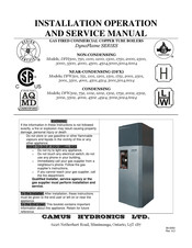
Camus Hydronics DFH1200 Installation, Operation And Service Manual (70 pages)
GAS FIRED COMMERCIAL COPPER TUBE BOILERS
Brand:
Camus Hydronics
| Category:
Boiler
| Size: 3.4 MB
Table of Contents
Table of Contents
3
Part 1 General Information
6
Overview
6
Introduction
6
Special Instructions to Owner
6
Checking Equipment
7
What the Lights Mean on Your Camus Appliance
7
How It Operates (Sequence of Operation)
7
Ignition Process
8
Heat Transfer Process
8
End of Sequence
8
Codes
9
Warranty
9
Removal of Existing Appliance
9
Boiler Room Operating Condition
10
Clearance from Combustible Material
10
Installation Procedure Location of Unit
11
Part 2 Venting
13
General Venting Guide
13
CATEGORY I and CATEGORY Ill VENTING
13
Venting Guidelines for Category Iand/Or III Venting
14
Category II and Category IV Venting
14
Venting Guidelines for Category II And/Or IV Venting
14
Approved Venting Materials
14
Vent Termination Clearances
14
Inlet Cap for Rooftop Termination
15
Location of a Rooftop Air Inlet and Vent Caps
15
Air Inlet Damper
15
Masonary Chimney Insulations
15
Vertical Venting Termination
15
Combined Combustion Air Inlet
15
Drain Tee
16
Conventional Venting (Indoor) Installations
16
Air Required for Combustion and Ventilation
17
Exhaust Fans
17
Outdoor Venting
17
Thruwall Venting
17
Thruwall Vent Cap (14-0090) Thruwall Intake Air Cap (14-0101)
17
Location of a Thruwall Vent Termination
18
Location of a "Thruwall" Air Inlet Cap
18
Length of Air Inlet Pipe
18
Part 3 Gas Connection
18
Gas Connection
18
Gas Piping
19
Install Piping
19
Differential Air Pressure
19
Gas Manifold Differential Pressure Adjustment
19
Checking Gas Supply Pressure
20
Checking Differential Air and Gas Pressures
20
Gas Train and Controls
21
Ratio Gas Valve
21
Venting of Gas Valves and Pressure Switches
21
Burner
21
Part 4 Water Connection
22
Freeze Protection
22
Warning Regarding Chilled Water Systems
22
Inlet and Outlet Connections
23
Minimum Pipe Size Requirements
23
Primary Heat Exchanger
23
Low Water Temperature Systems
23
INSTANTANEOUS WATER HEATER (Non-Condensing)
24
Condenser Heat Recovery Module (Chrm)
24
CHRM, FLOW and PRESSURE DROP
25
WATER FLOW SWITCH (Shipped Loose)
25
LOW WATER CUTOFF (if Equipped)
26
RELIEF VALVE (Shipped Loose)
26
Condensing Heat Recovery Module Piping Configurations
26
Chrm in Series with Primary Heat Exchanger (Integrated Loop)
26
Circulating Pump Selection
26
Circulating Pump Operation Primary Heat Exchanger
26
Circulating Pump Selection Condensor
26
Part 5 Electrical & Controls
27
Electrical Conections
27
Variable Frequency Drive (Vfd)
27
Diffrential Air Pressure Switch
27
Blocked Flue Switch
27
HIGH and LOW GAS PRESSURE SWITCHES (Optional)
28
High Limit
28
Ignition Control Module
28
Service Parts
28
Ignition Module Lockout Functions
28
Diagnostic Status Indication
29
Flame Sense Test
29
Part 6 Control Panel
29
Appliance Temperature Controller
29
Variable Frequency Drive (Vfd)
34
Dynaflame Control Panel
35
General Symbol Description
35
Mode 1 & 2: Setpoint Operation: View Display
36
Mode 1 & 2: Setpoint Operation: Adjust Display
37
Mode 3: Dedicated Domestic Hot Water Operation: View Display
38
Mode 3: Dedicated Domestic Hot Water Operation: Adjust Display
39
Mode 4 & 5: Outdoor Reset Operation: View Display
40
Mode 4 & 5: Outdoor Reset Operation: Adjust Display
41
Mode 6 & 7: External Target Temperature Input Operation: View Display
42
Mode 6 & 7: External Target Temperature Input Operation: Adjust Display
43
Mode 8: External Drive Opeation: View Display
44
Mode 8: External Drive Opeation: Adjust Display
45
Error Messages
45
Part 7 Components
47
Hot Surface Igniter (Glow Bar)
47
Flame Sensor
47
Combustion Air Fan
47
Inner Jacket
47
Outer Jacket
47
Venting Transition
47
Part 8 Field Startup Procedure
48
Checking the Installation
48
Checking the Construction
48
Fire Testing
48
Comissioning Appliance
49
Part 9 Trouble Shooting
50
Part 10 Maintanance
52
Examine the Venting System
52
Visually Check Main Burner Flames
52
Flue Gas Passageways Cleaning Procedures
52
Condensation Treatment
52
Condensate Volume
52
Burner Maintenance
53
Burner Removal and Cleaning
53
Burner Cleaning Procedure
53
Changing the Hot Surface Igniter
53
Re-Installing the Igniter
54
Primary Heat Exchanger Inspection
54
Condensing Heat Recovery Module (Chrm) Inspection
54
Re-Install Heat Exchangers
54
Combustion Air Fan
54
Combustion and Ventilation Air
54
Control Circuit Voltage
54
Combustible Materials
54
Freeze Protection
54
FREEZE PROTECTION for a HEATING BOILER SYSTEM (Optional)
55
Part 11 Installations
55
Heating Boiler Installations
55
Water Connections
55
Piping Lengths
55
Intermittent Pump Operation
55
Summary
56
Domestic Hot Water Heater
56
Water Velocity Control
56
Temperature Rise at Full Firing Rate
56
Water Heaters
57
Part 12 Exploded View
58
Part 13 Electrical Diagrams
66
Warranty
69
Advertisement
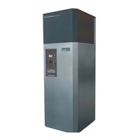
Camus Hydronics DFH1200 Installation, Operation And Service Manual (53 pages)
Gas Fired Commercial Copper Tube Boilers Dynaflame Series
Brand:
Camus Hydronics
| Category:
Boiler
| Size: 3.24 MB
Table of Contents
Table of Contents
2
Part 1 General Information
4
Introduction
4
Special Instructions to Owner
4
Checking Equipment
4
What the Lights Mean on Your Camus Appliance
5
How It Operates (Sequence of Operation)
5
Ignition Process
6
Heat Transfer Process
6
End of Sequence
6
Codes
6
Warranty
7
Removal of Existing Appliance
7
Boiler Room Operating Condition
8
Installation Procedure Location of Unit
8
Clearance from Combustible Material
8
Part 2 Venting
10
General Venting Guide
10
CATEGORY I and CATEGORY Ill VENTING
10
Venting Guidelines for Category I And/Or Ill Venting
10
Category II and Category IV Venting
11
Venting Guidelines for Category II And/Or IV Venting
11
Approved Venting Materials
11
Vent Termination Clearances
11
Inlet Cap for Rooftop Termination
11
Location of a Rooftop Air Inlet and Vent Caps
11
Air Inlet Damper
12
Masonary Chimney Insulations
12
Vertical Venting Termination
12
Combined Combustion Air Inlet
12
Drain Tee
12
Conventional Venting (Indoor) Installations
13
Air Required for Combustion and Ventilation
13
Exhaust Fans
13
Outdoor Venting
14
Thruwall Venting
14
THRUWALL Vent Cap (14-0090) THRUWALL Intake Air Cap (14-0101)
14
Location of a THRUWALL Vent Termination
14
Location of a "Thruwall" Air Inlet Cap
15
Air Inlet Damper
15
Length of Air Inlet Pipe
15
Part 3 Gas Connection
15
Gas Connection
15
Gas Piping
16
Install Piping
16
Differential Air Pressure
16
Gas Manifold Differential Pressure Adjustment
16
Checking Gas Supply Pressure
17
Checking Differential Air and Gas Pressures
17
Gas Train and Controls
18
Ratio Gas Valve
18
Venting of Gas Valves and Pressure Switches
18
Burner
18
Part 4 Water Connection
19
Freeze Protection
19
Warning Regarding Chilled Water Systems
19
Inlet and Outlet Connections
20
Minimum Pipe Size Requirements
20
Primary Heat Exchanger
20
LOW WATER TEMPERATURE SYSTEMS (Non -Condensing)
20
INSTANTANEOUS WATER HEATER (Non-Condensing)
21
Condenser Heat Recovery Module (Chrm)
21
CHRM, FLOW and PRESSURE DROP
22
WATER FLOW SWITCH (Shipped Loose)
22
LOW WATER CUTOFF (if Equipped)
22
RELIEF VALVE (Shipped Loose)
23
Condensing Heat Recovery Module Piping Configurations
23
Chrm in Series with Primary Heat Exchanger (Integrated Loop)
23
Circulating Pump Selection
23
Circulating Pump Operation Primary Heat Exchanger
23
Circulating Pump Selection Condensor
23
Part 5 Electrical & Controls
24
Electrical Conections
24
Variable Frequency Drive (Vfd)
24
Diffrential Air Pressure Switch
24
HIGH and LOW GAS PRESSURE SWITCHS (Optional)
24
High Limit
24
Ignition Control Module
24
Service Parts
25
Ignition Module Lockout Functions
25
Diagnostic Status Indication
25
Flame Sense Test
25
Part 6 Control Panel
26
Appliance Temperature Controller
26
Modulating Signal Generator
28
Variable Frequency Drive (Vfd)
28
Part 7 Components
28
Hot Surface Igniter (Glow Bar)
28
Flame Sensor
28
Combustion Air Fan
29
Inner Jacket
29
Outer Jacket
29
Venting Transition
29
Part 8 Field Startup Procedure
29
Checking the Installation
29
Checking the Construction
29
Fire Testing
30
Comissioning Appliance
30
Part 9 Trouble Shooting
31
Part 10 Maintanance
33
Examine the Venting System
33
Visually Check Main Burner Flames
33
Flue Gas Passageways Cleaning Procedures
33
Condensation Treatment
33
Condensate Volume
33
Burner Maintenance
34
Burner Removal and Cleaning
34
Burner Cleaning Procedure
34
Changing the Hot Surface Igniter
34
Re-Installing the Igniter
35
Primary Heat Exchanger Inspection
35
Condensing Heat Recovery Module (Chrm) Inspection
35
Re-Install Heat Exchangers
35
Combustion Air Fan
35
Combustion and Ventilation Air
35
Control Circuit Voltage
35
Combustible Materials
35
Freeze Protection
35
FREEZE PROTECTION for a HEATING BOILER SYSTEM (Optional)
36
Part 11 Installations
36
Heating Boiler Installations
36
Water Connections
36
Piping Lengths
36
Intermittent Pump Operation
36
Summary
36
Domestic Hot Water Heater
37
Water Velocity Control
37
Temperature Rise at Full Firing Rate
37
Water Heaters
38
Part 12 Exploded View
39
Part 13 Electrical Diagrams
46
Warranty
52
Advertisement
Related Products
Camus Hydronics DFH1500
Camus Hydronics DFH1750
Camus Hydronics DFH1100
Camus Hydronics DFH3000
Camus Hydronics DFH4000
Camus Hydronics DFH5000
Camus Hydronics DFH/W750
Camus Hydronics DFH501
Camus Hydronics DFH/W4502
Camus Hydronics DFH/W1102
Camus Hydronics Categories
Boiler
Water Heater
Gas Heater
Controller
More Camus Hydronics Manuals
Login
Sign In
OR
Sign in with Facebook
Sign in with Google
Upload manual
Upload from disk
Upload from URL