Sign In
Upload
Manuals
Brands
Campbell Manuals
Data Loggers
CR3000 Micrologger
Campbell CR3000 Micrologger Data Logger Manuals
Manuals and User Guides for Campbell CR3000 Micrologger Data Logger. We have
2
Campbell CR3000 Micrologger Data Logger manuals available for free PDF download: Operator's Manual, Quick Using Manual
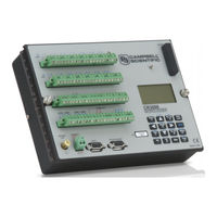
Campbell CR3000 Micrologger Operator's Manual (644 pages)
Brand:
Campbell
| Category:
Data Loggers
| Size: 13 MB
Table of Contents
Table of Contents
9
1 Introduction
31
Hello
31
Typography
32
Capturing Crbasic Code
32
2 Precautions
33
3 Initial Inspection
35
4 Quickstart
37
Sensors - Quickstart
37
Datalogger - Quickstart
38
CR3000 Module
38
Wiring Panel - Quickstart
38
Power Supplies - Quickstart
39
FIGURE 1: Wiring Panel
39
Internal Battery - Quickstart
40
Data Retrieval and Comms - Quickstart
40
Datalogger Support Software - Quickstart
41
Datalogger Support Software - List
41
Tutorial: Measuring a Thermocouple
42
What You will Need
42
Hardware Setup
42
Connect External Power Supply
43
Connect Internal Power Supply
43
FIGURE 2: Connect Power and Comms (Internal-Power Supply)
43
Connect Comms
44
PC200W Software Setup
44
FIGURE 3: Connect Power and Comms (External-Power Supply)
44
FIGURE 4: PC200W Main Window
45
PC200W Ezsetup Wizard Prompts
45
Write Crbasic Program with Short Cut
46
Procedure: (Short Cut Steps 1 to 5)
46
FIGURE 5: Short Cut Temperature Sensor Folder
47
Procedure: (Short Cut Step 8)
47
Procedure: (Short Cut Steps 6 to 7)
47
Procedure: (Short Cut Steps 13 to 14)
48
Procedure: (Short Cut Steps 9 to 12)
48
Send Program and Collect Data
49
Procedure: (PC200W Step 1)
49
Procedure: (PC200W Steps 2 to 4)
50
Procedure: (PC200W Step 5)
51
Procedure: (PC200W Step 6)
52
Procedure: (PC200W Steps 7 to 10)
53
Procedure: (PC200W Steps 11 to 12)
54
Procedure: (PC200W Steps 13 to 14)
54
Data Acquisition Systems - Quickstart
55
FIGURE 15: Data Acquisition System Components
56
5 Overview
57
Datalogger - Overview
58
Wiring Panel - Overview
59
FIGURE 17: Wiring Panel
60
CR3000 Wiring Panel Terminal Definitions, 2
61
Switched Voltage Output - Overview
62
Voltage and Current Excitation - Overview
62
Power in Terminals
63
Power out Terminals
63
Power Terminals
63
Communication Ports - Overview
64
CS I/O Port
65
Peripheral Port
65
Ports
65
CPI Port and CDM Devices - Overview
66
Ethernet Port
66
Grounding - Overview
66
SDM Port
66
Measurements - Overview
67
Time Keeping - Overview
67
Analog Measurements - Overview
67
Voltage Measurements - Overview
68
FIGURE 19: Analog Sensor Wired to Single-Ended Channel #1
69
Single-Ended Measurements - Overview
70
Differential Measurements - Overview
71
Current Measurements - Overview
72
Resistance Measurements - Overview
72
Voltage Excitation
72
Current Excitation
73
Strain Measurements - Overview
74
Pulse Measurements - Overview
74
Pulses Measured
74
Pulse Input Channels
75
Pulse Sensor Wiring
75
Pulse Input Terminals and Measurements
75
Period Averaging - Overview
76
Vibrating Wire Measurements - Overview
77
Reading Smart Sensors - Overview
77
Overview
78
SDI-12 Sensor Support — Overview
78
Sensor Support - Overview
78
Field Calibration - Overview
79
Cabling Effects - Overview
79
Synchronizing Measurements - Overview
79
Synchronizing Measurements in a Datalogger Network - Overview
80
Synchronizing Measurements in the CR3000 - Overview
80
Data Retrieval and Comms - Overview
80
Data File Formats in CR3000 Memory
80
Data Format on Computer
80
Mass-Storage Device
80
Memory Card (CRD: Drive) - Overview
81
Comms
81
Direct with Adapter to PC
81
Comms Protocols
82
Pakbus Comms - Overview
82
Alternate Comms Protocols - Overview
82
DNP3 - Overview
83
Modbus - Overview
83
TCP/IP - Overview
84
Comms Hardware - Overview
84
Keyboard/Display - Overview
84
Character Set
85
Custom Menus - Overview
85
Integrated Keyboard/Display
85
Measurement and Control Peripherals - Overview
86
Power Supplies - Overview
86
CR3000 Setup - Overview
87
Crbasic Programming - Overview
87
Security - Overview
88
Maintenance - Overview
89
Protection from Moisture - Overview
89
Protection from Voltage Transients - Overview
89
Factory Calibration - Overview
89
Internal Battery - Overview
90
Datalogger Support Software - Overview
90
PLC Control - Overview
91
Auto Self-Calibration - Overview
92
Memory - Overview
93
6 Specifications
95
7 Installation
97
Enclosures - Details
97
Power Supplies - Details
98
CR3000 Power Requirement
99
Calculating Power Consumption
99
Power Sources
99
Vehicle Power Connections
100
Uninterruptable Power Supply (UPS)
101
External Power Supply Installation
101
External Alkaline Power Supply
101
Integrated Batteries
101
Alkaline-Battery Base
102
Sealed Rechargeable-Battery Base
103
Alkaline Battery Temperatures and Service
103
CR3000 Base Sealed-Rechargeable Battery Specifications
105
Low Profile (no Battery) Base
106
Grounding - Details
106
CR3000 Ac-Transformer Specifications
106
ESD Protection
107
Lightning Protection
108
Single-Ended Measurement Reference
109
Ground Potential Differences
110
External Signal Conditioner
110
Soil Temperature Thermocouple
110
Ground Looping in Ionic Measurements
111
Protection from Moisture - Details
112
CR3000 Setup - Details
112
Tools - Setup
113
Devconfig - Setup Tools
113
Network Planner - Setup Tools
114
Overview - Network Planner
115
Basics - Network Planner
116
Info Tables and Settings - Setup Tools
117
Crbasic Program - Setup Tools
118
Executable CPU: Files - Setup Tools
118
Default.cr3 File
119
Include" File
119
FIGURE 37: "Include" File Settings with Devconfig
120
FIGURE 38: "Include" File Settings with Pakbusgraph
121
Executable File Run Priorities
122
Setup Tasks
123
Common Configuration Actions and Tools
123
Operating System (OS) - Details
123
OS Update with Devconfig Send os Tab
124
OS Update with File Control
125
OS Update with Send Program Command
126
Program Send Command Locations
126
OS Update with External Memory and Powerup.ini File
127
Factory Defaults - Installation
128
Saving and Restoring Configurations - Installation
128
Crbasic Programming - Details
129
Program Structure
129
Crbasic Program Structure
130
Writing and Editing Programs
132
Crbasic Editor
132
Short Cut Programming Wizard
132
Inserting Comments into Program
133
Conserving Program Memory
134
Programming Syntax
134
Program Statements
134
Multiple Statements on One Line
135
One Statement on Multiple Lines
135
Single-Statement Declarations
135
Declaring Variables
136
Data Types in Final-Storage Memory
137
Declaring Data Types
137
Data Type Declarations
140
Dimensioning Numeric Variables
141
Declaring Flag Variables
142
Dimensioning String Variables
142
Using Variable Pointers
143
Declaring Arrays
144
Advanced Array Declaration
145
Declaring Local and Global Variables
146
Initializing Variables
146
Declaring Constants
147
Declaring Aliases and Units
148
Predefined Constants
148
Formats for Entering Numbers in Crbasic
149
Numerical Formats
149
Multi-Statement Declarations
150
Declaring Data Tables
151
TOA5 Environment Line
152
Typical Data Table
152
Declaration and Use of a Data Table
153
Datainterval() Lapse Parameter Options
156
Declaring Subroutines
158
Declaring Incidental Sequences
159
Declaring Subroutines
159
Execution and Task Priority
160
Program Tasks
160
Pipeline Mode
161
Sequential Mode
162
Execution Timing
163
Program Timing Instructions
163
Scan() / Nextscan
163
Slowsequence / Endsequence
164
Scan Priorities in Sequential Mode
165
Subscan() / Nextsubscan
165
Measurement and Data Storage Processing
167
Programming Instructions
167
Argument Types
168
Names in Arguments
168
Expressions in Arguments
169
Rules for Names
169
Data Types in Variable Memory
170
Floating-Point Arithmetic
170
Programming Expression Types
170
Arithmetic Operations
171
Expressions with Numeric Data Types
171
Conversion of FLOAT / LONG to Boolean
172
Logical Expressions
173
Binary Conditions of TRUE and FALSE
174
Logical Expression Examples
175
String Expressions
176
Programming Access to Data Tables
177
Data Process Abbreviations
178
Functions (with a Capital F)
179
Programming to Use Signatures
179
Preserving Data at Program Send
180
Sending Crbasic Programs
180
Programming Resource Library
181
Advanced Programming Techniques
181
Capturing Events
181
Program Send Options that Reset Memory
181
Conditional Output
182
Groundwater Pump Test
183
Groundwater Pump Test
184
Miscellaneous Features
186
Pulsecountreset Instruction
188
Scaling Array
189
Binary Runtime Signature
190
Executable Code Signatures
190
Signatures: Example Programs
190
Text Signature
190
Use of Multiple Scans
191
Data Input: Loading Large Data Sets
192
Data Input: Array-Assigned Expression
193
Array Assigned Expression: Sum Columns and Rows
195
Array Assigned Expression: Comparison Boolean Evaluation
196
Data Output: Calculating Running Average
197
FIGURE 42: Running-Average Frequency Response
200
Data Output: Two Intervals in One Data Table
201
Data Output: Triggers and Omitting Samples
202
Data Output: Using Data Type Bool8
203
FIGURE 45: Alarms Toggled in Bit Shift Example
205
FIGURE 47: Bool8 Data from Bit Shift Example (PC Data File)
206
Data Output: Using Data Type NSEC
208
NSEC Options
208
NSEC — One Element Time Array
209
NSEC — Seven and Nine Element Time Arrays
210
Data Output: Wind Vector
211
Outputopt Parameters
212
Wind Vector Processing
212
Windvector() Outputopt Options
212
Measured Raw Data
213
Calculations
214
FIGURE 49: Mean Wind-Vector Graph
215
FIGURE 50: Standard Deviation of Direction
216
Data Output: Writing High-Frequency Data to Memory Cards
217
Tablefile() with Option 64
218
Tablefile() with Option 64 Replaces Cardout()
218
Tablefile() with Option 64 Programming
219
Converting TOB3 Files with Cardconvert
220
Tablefile() with Option 64 Q & a
220
Displaying Data: Custom Menus - Details
222
FIGURE 52: Custom Menu Example — Home Screen
224
FIGURE 55: Custom Menu Example — Predefined Notes Pick List
225
FIGURE 58: Custom Menu Example — Control Sub Menu
226
Custom Menus
227
Field Calibration - Details
229
Field Calibration CAL Files
229
Field Calibration Programming
229
Field Calibration Numeric Monitor Procedures
230
Field Calibration Wizard Overview
230
Fieldcal() Codes
231
One-Point Calibrations (Zero or Offset)
231
Field Calibration Examples
232
Two-Point Calibrations (Gain and Offset)
232
Zero Basis Point Calibration
232
Fieldcal() Zero or Tare (Opt 0) Example
233
Fieldcal() Zero
234
Fieldcal() Offset (Opt 1) Example
235
Calibration Report for Salinity Sensor
236
Fieldcal() Offset
237
Fieldcal() Slope and Offset (Opt 2) Example
238
Fieldcal() Two-Point Slope and Offset
239
Fieldcal() Slope (Opt 3) Example
240
Calibration Report for Water Content Sensor
241
Fieldcal() Multiplier
242
Fieldcal() Zero Basis (Opt 4) Example
243
Field Calibration Strain Examples
243
Fieldcalstrain() Shunt Calibration Concepts
243
Fieldcalstrain() Shunt Calibration Example
244
FIGURE 61: Quarter-Bridge Strain Gage with RC Resistor Shunt
245
Fieldcalstrain() Quarter-Bridge Shunt Example
246
Fieldcalstrain() Quarter-Bridge Zero
247
Measurement: Fast Analog Voltage
248
Fast Analog Voltage Measurement: Fast Scan()
249
Analog Voltage Measurement: Cluster Burst
250
Dwell Burst Measurement
251
Tips - Fast Analog Voltage
252
Measurement: Excite, Delay, Measure
254
Serial I/O: SDI-12 Sensor Support - Details
255
Transparent Mode
255
Transparent Mode Commands
256
SDI-12 Commands for Transparent Mode
257
Recorder Mode
261
Alternate Start Concurrent Measurement Command
263
Using Sdi12Sensor() to Test CV Command
265
Using Alternate Concurrent Command (Ac)
266
Extended Command Support
267
Sensor Mode
268
SDI-12 Sensor Setup
269
Power Considerations
270
Compiling: Conditional Code
271
Conditional Code
272
Measurement: RTD, PRT, PT100, PT1000
273
Measurement Theory (PRT)
274
General Procedure (PRT)
275
PRT Measurement Circuit Overview
275
Callandar-Van Dusen Coefficients for PT100, Α = 0.00385
276
Example: 100 Ω PRT in Four-Wire Half Bridge with
277
FIGURE 67: PT100 Brhalf4W() Four-Wire Half-Bridge Schematic
277
Voltage Excitation (PT100 / Brhalf4W() )
277
PT100 Brhalf4W() Four-Wire Half-Bridge Calibration
280
Example: 100 Ω PRT in Three-Wire Half Bridge with
281
FIGURE 68: PT100 Brhalf3W() Three-Wire Half-Bridge Schematic
281
Voltage Excitation (PT100 / Brhalf3W() )
281
PT100 Brhalf3W() Three-Wire Half-Bridge Calibration
284
Example: 100 Ω PRT in Four-Wire Full Bridge with
285
FIGURE 69: PT100 Brfull() Four-Wire Full-Bridge Schematic
285
Voltage Excitation (PT100 / Brfull() )
285
PT100 Brfull() Four-Wire Full-Bridge Calibration
287
PT100 Brfull() Four-Wire Full-Bridge Calibration
288
PT100 Brfull() Four-Wire Full-Bridge Measurement
289
(PT100 / Basic Resistance() )
290
Example: 100 Ω PRT in Four-Wire Basic Circuit
290
FIGURE 70: PT100 Resistance() Basic-Circuit Schematic
291
PT100 Resistance() Basic-Circuit Calibration
293
Number of PT100
294
FIGURE 71: PT100 Resistance() Basic-Circuit Series Schematic
295
Resistance() )
296
Values
297
PT100 Resistance() Four-Wire Full-Bridge Calibration
299
PRT Callendar-Van Dusen Coefficients
300
Prtcalc() Prttype = 3, Α = 0.00391 1
302
Self-Heating and Resolution
303
Serial I/O: Capturing Serial Data
303
Introduction
304
I/O Ports
305
Glossary of Serial I/O Terms
306
Protocols
306
Serial I/O Crbasic Programming
308
Serial I/O Programming Basics
309
Serial I/O Input Programming Basics
311
Serial I/O Output Programming Basics
312
Serial I/O Translating Bytes
313
Serial I/O Memory Considerations
314
Serial I/O Example I
315
Configure Hyperterminal
316
Serial I/O Application Testing
316
FIGURE 73: Hyperterminal New Connection Description
317
FIGURE 75: Hyperterminal COM Port Settings Tab: Click File Properties | Settings | ASCII Setup... and Set as Shown
318
Create Send-Text File
319
Create Text-Capture File
319
Serial I/O Example II
319
Measure Sensors / Send RS-232 Data
320
Serial I/O Q & a
325
String Operations
327
String Operators
328
String Concatenation
329
String NULL Character
331
Inserting String Characters
332
Subroutines
332
Subroutine with Global and Local Variables
333
8 Operation
335
Measurements - Details
335
Time Keeping - Details
335
Time Stamps
335
Time Stamping with System Time
336
Analog Measurements - Details
337
Voltage Measurement Quality
337
FIGURE 79: Ac Power Noise Rejection Techniques
340
Ac Noise Rejection on Small Signals 1
341
FIGURE 80: Input Voltage Rise and Transient Decay
343
Measuring Settling Time
344
FIGURE 81: Settling Time for Pressure Transducer
345
First Six Values of Settling Time Data
346
Range-Code Option C Over-Voltages
347
Offset Voltage Compensation Options
349
Analog Voltage Measurement Accuracy 1
352
Analog Voltage Measurement Resolution
353
Measurement with Input Reversal at a Temperature between 0 to 40 °C
354
Thermocouple Measurements - Details
355
Thermocouple Error Analysis
356
FIGURE 83: Panel Temperature Error Summary
358
FIGURE 85: Panel Temperature Gradients (High Temperature to Low)
359
Limits of Error for Thermocouple Wire (Reference Junction
360
FIGURE 86: Input Error Calculation
361
Limits of Error on CR3000 Thermocouple Polynomials
364
Reference Temperature Compensation Range and Error
365
Use of External Reference Junction
366
Resistance Measurements - Details
367
Resistive-Bridge Circuits with Voltage Excitation
368
Resistive-Bridge Circuits with Current Excitation 1
370
Ac Excitation
371
Accuracy - Resistance Measurements
371
Ratiometric-Resistance Measurement Accuracy
372
Auto Self-Calibration - Details
373
Auto Self-Calibration Process
373
Calgain() Field Descriptions
375
Caldiffoffset() Field Descriptions
376
Calibrate() Instruction Results
377
Strain Measurements - Details
378
Straincalc() Instruction Equations
379
Current Measurements - Details
380
Voltage Measurements - Details
380
Voltage Measurement Limitations
380
Analog Voltage Input Ranges and Options
381
Voltage Measurement Mechanics
383
FIGURE 90: Programmable Gain Input Amplifier (PGIA): H to V+, L to V–, VH to V+, VL to V– Correspond to Text
384
Timing
385
Voltage Measurement Quality
386
Analog Measurement Integration
389
FIGURE 91: Ac Power Noise Rejection Techniques
390
Ac Noise Rejection on Large Signals 1
391
FIGURE 92: Input Voltage Rise and Transient Decay
392
Measuring Settling Time
394
FIGURE 93: Settling Time for Pressure Transducer
395
Range-Code Option C Over-Voltages
396
Offset Voltage Compensation Options
399
Analog Voltage Measurement Accuracy 1
401
Analog Voltage Measurement Offsets
402
Measurement with Input Reversal at a Temperature between 0 to 40 °C
403
Pulse Measurements - Details
404
FIGURE 95: Pulse Sensor Output Signal Types
405
FIGURE 97: Terminals Configurable for Pulse Input
406
Low-Level Ac Measurements - Details
407
Pulse Measurement Terminals
407
High-Frequency Measurements
408
Frequency Resolution
409
Frequency Measurement Q & a
410
Switch Closure and Open-Collector Measurements
410
Edge Timing
411
Edge Counting
412
Pulse Measurement Tips
412
Timer Input on I/O NAN Conditions
412
Switch Closures and Open Collectors on P Terminals
413
Pay Attention to Specifications
414
Input Filters and Signal Attenuation
415
FIGURE 98: Amplitude Reduction of Pulse Count Waveform (before and after 1 Μs Μs Time- Constant Filter)
416
Time-Domain Measurement
417
Vibrating Wire Measurements - Details
417
Period Averaging - Details
418
And TTL - Details
419
Reading Smart Sensors - Details
419
Field Calibration - Overview
420
SDI-12 Sensor Support — Details
420
Sensor Support - Details
420
Analog Sensor Cabling
421
Cabling Effects - Details
421
Current Excitation Cabling
421
Pulse Sensor Cabling
421
Sensor Cabling
422
Synchronizing Measurement in the CR3000 - Details
422
Synchronizing Measurements - Details
422
Synchronizing Measurements in a Datalogger Network - Details
422
Switched-Voltage Output - Details
424
Switched-Current Excitation (IX Terminals)
425
Switched-Voltage Excitation
425
Continuous-Analog out (CAO Terminal)
426
Continuous-Regulated (5V Terminal)
426
Continuous-Unregulated Voltage (12V Terminal)
426
Switched-Unregulated Voltage (SW12 Terminal)
426
PLC Control - Details
427
Terminals Configured for Control
428
Measurement and Control Peripherals - Details
429
Analog Input Modules
429
Analog Output Modules
430
Component-Built Relays
430
PLC Control Modules - Overview
430
Relays and Relay Drivers
430
Low-Level Ac Input Modules - Overview
431
Pulse Input Modules
431
Serial I/O Modules - Details
432
Terminal-Input Modules
432
Vibrating Wire Modules
432
Datalogger Support Software - Details
432
Program and os File Compression Q and a
433
Security - Details
436
Vulnerabilities
437
Pass-Code Lockout
438
Pass-Code Lockout By-Pass
439
Csipasswd
440
Pakbus Instructions
440
Passwords
440
TCP/IP Instructions
440
Communication Encryption
441
File Encryption
441
Hiding Files
441
Settings - Passwords
441
Read Only Variables
442
Signatures
442
Memory - Details
442
Storage Media
442
CR3000 Memory Allocation
443
CR3000 SRAM Memory
444
Memory Drives - On-Board
445
CPU: Drive
446
Data Table SRAM
446
USR: Drive
446
Memory Card (CRD: Drive)
447
USB: Drive
447
Data File Formats
449
Memory Cards and Record Numbers
453
Resetting the CR3000
454
Full Memory Reset
455
Manual Data-Table Reset
455
Program Send Reset
455
File Management in CR3000 Memory
456
Formatting Drives
456
File Attributes
457
Files Manager
458
Data Preservation
459
Powerup.ini File - Details
460
Creating and Editing Powerup.ini
461
Powerup.ini Script Commands and Applications
462
File Management Q & a
464
File Names
464
File System Errors
464
Memory Q & a
466
Data Retrieval and Comms - Details
466
Conserving Bandwidth
466
Protocols
466
Initiating Comms (Callback)
467
Alternate Comms Protocols
468
TCP/IP - Details
468
Dhcp
469
Dns
469
FTP Server
469
Fyis - OS2; OS28
469
Default HTTP Web Server
470
FTP Client
470
HTTP Web Server
470
Custom HTTP Web Server
471
FIGURE 108: Customized Numeric-Monitor Web
472
Micro-Serial Server
473
Modbus TCP/IP
473
Pakbus over TCP/IP and Callback
474
Ping (IP)
474
Snmp
474
Telnet
474
DNP3 - Details
475
Smtp
475
Web API
475
Web API - Details
475
Modbus - Details
476
Modbus Terminology
476
Declarations (Modbus Programming)
477
Glossary of Modbus Terms
477
Programming for Modbus
477
Crbasic Instructions (Modbus)
478
Addressing (Modbusaddr)
479
Supported Modbus Function Codes
479
Modbus over IP
480
Reading Inverse Format Modbus Registers
480
Timing
480
Troubleshooting (Modbus)
480
Modbus Security
481
Converting Modbus 16-Bit to 32-Bit Longs
482
Modbus over RS-232 7/E/1
482
Keyboard/Display - Details
483
Character Set
483
FIGURE 109: Keyboard and Display: Navigation
484
Data Display
485
Real-Time Custom
486
Real-Time Tables and Graphs
486
FIGURE 112: CR1000KD Real-Time Custom
487
Final-Storage Data
488
Run/Stop Program
489
File Edit
490
File Management
490
FIGURE 116: Keyboard and Display: File Edit
491
Pccard (Memory Card) Management
492
Port Status and Status Table
492
Settings
493
Configure Display
494
CR1000KD: Pakbus Settings
494
CR1000KD: Set Time / Date
494
CPI Port and CDM Devices - Details
494
9 Maintenance - Details
497
Protection from Moisture - Details
497
Internal Battery - Details
497
FIGURE 121: Loosen Thumbscrews
498
FIGURE 122: Remove Back Cover Retainer Screw
499
Factory Calibration or Repair Procedure
500
10 Troubleshooting
503
Troubleshooting - Essential Tools
503
Troubleshooting - Basic Procedure
503
Troubleshooting - Error Sources
504
Troubleshooting - Status Table
505
Troubleshooting - Crbasic Programs
505
Program Does Not Compile
505
Program Compiles / Does Not Run Correctly
506
NAN and ±INF
506
Data Types, NAN, and ±INF
507
Floating-Point Math, NAN, and ±INF
507
Measurements
507
Measurements and NAN
507
Voltage Measurements
507
Math Expressions and Crbasic Results
508
Output Processing and NAN
509
Status Table as Debug Resource
510
Compileresults
510
Warning Message Examples
511
Skippedscan
512
Skippedsystemscan
513
Skippedrecord
513
Progerrors
513
Memoryfree
513
Varoutofbounds
513
Watchdog Errors
514
Status Table Watchdogerrors
514
Watchdoginfo.txt File
515
Troubleshooting - Operating Systems
515
Troubleshooting - Auto Self-Calibration Errors
515
Troubleshooting - Communications
516
516
516
Communicating with Multiple Pcs
516
Comms Memory Errors
517
Troubleshooting - Power Supplies
517
Troubleshooting Power Supplies - Overview
517
Troubleshooting Power Supplies - Examples
518
Troubleshooting Power Supplies - Procedures
518
Battery Test
518
Charging Regulator with Solar Panel Test
519
Charging Regulator with Transformer Test
521
Adjusting Charging Voltage
522
Troubleshooting - Using Terminal Mode
523
CR3000 Terminal Commands
524
Serial Talk through and Comms Watch
526
Troubleshooting - Using Logs
526
Troubleshooting - Data Recovery
526
Troubleshooting - Miscellaneous Errors
527
Voltage Calibration Error
527
Troubleshooting - Rebooting
528
11 Glossary
529
Terms
529
Program Send Command
551
Concepts
563
Accuracy, Precision, and Resolution
563
12 Attributions
565
Info Tables and Settings
567
Info Tables and Settings Directories
569
Info Tables and Settings: Frequently Used
569
Info Tables and Settings: Keywords
570
Info Tables and Settings: Accessed by Keyboard/Display
572
Info Tables and Settings: KD Status Table Fields
573
Info Tables and Settings: Communications
574
Info Tables and Settings: Programming
575
Info Tables and Settings: Other
575
Info Tables and Settings Descriptions
576
Info Tables and Settings: B
577
Info Tables and Settings: D
580
Info Tables and Settings: E
581
Info Tables and Settings: H
582
Info Tables and Settings: L
583
Info Tables and Settings: M
584
Info Tables and Settings: N
585
Info Tables and Settings: O
586
Info Tables and Settings: R
588
Info Tables and Settings: S
589
Info Tables and Settings: T
591
Info Tables and Settings: U
592
Info Tables and Settings: W
593
Serial Port Pinouts
595
CS I/O Communication Port
595
Communication Port
596
Pin Outs
596
B.2 RS-232 Communication Port
596
Power States
597
FP2 Data Format
599
Endianness
601
Supporting Products - List
603
Dataloggers - List
603
Measurement and Control Peripherals - List
604
Sensor-Input Modules - List
604
Analog Input Modules - List
604
Pulse Input Modules - List
604
Serial I/O Modules - List
605
Vibrating Wire Input Modules - List
605
Passive Signal Conditioners - List
605
Current-Shunt Modules - List
606
Resistive-Bridge TIM Modules - List
606
Transient Voltage Suppressors - List
606
Voltage Divider Modules - List
606
Terminal Strip Covers - List
607
PLC Control Modules - Lists
607
Digital-I/O Modules - List
607
Continuous-Analog Output (CAO) Modules - List
607
Relay-Drivers - List
608
Current-Excitation Modules - List
608
Sensors - Lists
609
Wired-Sensor Types - List
609
Wireless-Network Sensors - List
610
Cameras - List
610
Data Retrieval and Comms Peripherals - List
610
Keyboard/Display - List
611
Hardwire, Single-Connection Comms Devices - List
611
Hardwire, Networking Devices - List
612
TCP/IP Links - List
612
Telephone Modems - List
612
Private-Network Radios - List
613
Satellite Transceivers - List
613
Data Storage Devices - List
613
Starter Software - List
614
E.9 Datalogger Support Software — List
614
E.9.2 Datalogger Support Software — List
615
Loggernet Suite - List
616
Software Tools - List
617
Software Development Kits - List
617
Power Supplies - List
618
Battery / Regulator Combinations - List
618
Batteries - List
619
CR3000 Battery Bases - List
619
Regulators - List
620
Primary Power Sources - List
620
Regulator
620
E.10.3 Regulators — List
620
24 VDC Power Supply Kits - List
621
Enclosures - List
621
Tripods, Towers, and Mounts - List
622
Protection from Moisture - List
622
Index
625
Advertisement
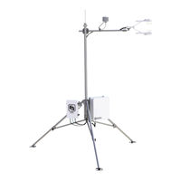
Campbell CR3000 Micrologger Quick Using Manual (12 pages)
Open Path Eddy Covariance System With IRGASON or EC150/CSAT3A
Brand:
Campbell
| Category:
Measuring Instruments
| Size: 1 MB
Advertisement
Related Products
Campbell CR300-RF407
Campbell CR300-RF412
Campbell CR300-RF422
Campbell CR300-CELL
Campbell CR300-RF427
Campbell CR300-WIFI
Campbell CR310
Campbell CR310-RF407
Campbell CR310-RF412
Campbell CR310-RF422
Campbell Categories
Measuring Instruments
Accessories
Modem
Weather Station
Recording Equipment
More Campbell Manuals
Login
Sign In
OR
Sign in with Facebook
Sign in with Google
Upload manual
Upload from disk
Upload from URL