Sign In
Upload
Manuals
Brands
Caltest Manuals
Portable Generator
LXI 3600AFX
Caltest LXI 3600AFX Manuals
Manuals and User Guides for Caltest LXI 3600AFX. We have
1
Caltest LXI 3600AFX manual available for free PDF download: Manual
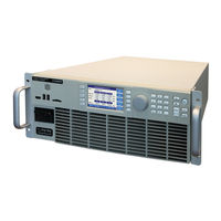
Caltest LXI 3600AFX Manual (402 pages)
Programmable Power Source
Brand:
Caltest
| Category:
Portable Generator
| Size: 8.67 MB
Table of Contents
Table of Contents
3
1 Contact Information
14
2 Safety & Warranty Information
15
Limited Warranty
15
Service and Spare Parts Limited Warranty
15
Safety Information
15
Safety Notices
17
3 Product Overview
21
General Description
21
Figure 3-1: AFX Series Model Number Decoder
21
Product Features
22
Block Diagram
23
Figure 3-2: AFX Series® Basic Block Diagram
23
Controller Description
24
Measurement Read-Back
24
Accessories Included (Ship Kit)
24
Remote Control Interfaces
24
Table 3-1: Included Accessories
24
Table 3-2: Remote Control Interface Options
24
4 Technical Specifications
25
Single Chassis Models
25
Multiple Chassis Models
25
AC Output Mode
26
Figure 4-1: Output Voltage Distortion into Full R Load as a Function of Frequency
27
Figure 4-2: 1.00Hz ~ 15.00Hz Freq. Range Power Rating in 3 Phs Mode
28
Figure 4-3: 1200Hz ~ 3000Hz Freq. Range Voltage Vs. Current- 3150AFX in 3 Phs Mode
28
Figure 4-4: 1200Hz ~ 3000Hz Extended Freq. Range Power - 3150AFX in 3 Phs Mode
29
Figure 4-5: Current Overload Vs. Time
29
Figure 4-6: AC Mode Voltage/Current Range, AFX Models - 3 or 2-Phase Mode
30
Figure 4-7: AC Mode Voltage/Current Range, AFX Models - 1 Phase Mode
30
Figure 4-8: Extended AC Voltage/Current Range, AFX Models - 3 or 2 Phase Mode
31
Figure 4-9: Extended AC Voltage/Current Range, AFX Models - 1 Phase Mode
31
DC Output Mode
32
Figure 4-10: DC Mode Voltage/Current Range, AFX Models- 3 or 2 Phase Mode
32
Figure 4-11: DC Mode Voltage/Current Range, AFX Models - 1 Phase Mode
33
Protection Modes
34
Metering
35
Other Measurements
36
Transients
36
AC Input
37
Dimensions & Weight
37
Environmental
38
Safety & Regulatory
38
Figure 4-12: Dimension Drawing AFX Series® 15KW Model
38
Digital Interfaces
39
Auxiliary I/O
40
Transformer Output Voltage Range (T Option)
41
Available T Option Rating Versions
41
Figure 4-13: Rack Mount Chassis for 6Kva to 15Kva Transformer Option
41
Technical Specifications 400V Range
42
Figure 4-14: Voltage Vs Current Rating 400V Range - 3 Phase Mode
43
Figure 4-15: Voltage Vs Current Rating 400V Range - 1 Phase Mode
43
5 Unpacking and Installation
44
Inspection
44
Lifting and Carrying Instructions
44
Figure 4-1: Model 5L18-36 VI Curve
44
Figure 5-2: Exploded View of AFX Unit Packaging
45
Verify Correct AC Input Line Voltage
46
AC Input Connections
47
Table 5-1: AC Input Wire Size Table
48
Figure 5-3: Rear Panel Layout
48
Grounding Requirements
49
Chassis Ground Connection Required
49
Figure 5-4: AC Input Terminal Block - Rear Panel
49
Output Neutral Grounding
50
AC Input Circuit Breaker
50
Figure 5-5: Grounding Floating Neutral Output
50
Bench Use
51
Rack Mounting
51
Airflow
51
Sound Levels
52
Cleaning
53
Liquids
53
Load Connections
54
Output Wiring and Recommended Wire Sizing
54
Three Phase Wye Load Output Connection
55
Figure 5-6: Three Phase Wye Load Output Connections - Internal Voltage Sense
56
Figure 5-7: Three Phase Wye Load Output Connections - External Voltage Sense
57
Three Phase Delta Load Output Connection
58
Figure 5-8: Three Phase Delta Load Output Connections - Internal Voltage Sense
59
Figure 5-9: Three Phase Delta Load Output Connections - External Voltage Sense
60
Single Phase Load Output Connection
61
Figure 5-10: Optional AFX Single Phase Shorting Adaptor Assembly
61
Figure 5-11: Single Phase Load Output Connections
62
External Voltage Sense Connections
63
Figure 5-12: AFX a Version External Voltage Sense Connector
64
Powering up
65
In Case of Malfunction
65
Cabinet Systems Installation
66
Standard Cabinet Sizes
66
Tools Required
66
Dimensions
67
Figure 5-13: AFX Cabinet Dimensions
67
Cabinet System AC Input Connections
68
Recommended AC Input Wire Strip Lengths
68
Figure 5-14: AFX Cabinet AC Input Connection Diagram
69
Cabinet System AC Input Neutral
70
Cabinet System Grounding
70
Recommended AC Output Wire Strip Lengths
71
Cabinet Load Connections - Three Phase WYE Loads
71
Figure 5-15: WYE Load Connection Diagram
71
Cabinet Load Connections - Three Phase Delta Loads
72
Figure 5-16: Delta Load Connection Diagram
72
Cabinet Load Connections - Single Phase Loads
73
Figure 5-17: Single Phase Load Connection Diagram
73
AFX Cabinet Systems Turn on and Turn off Procedures
74
Cabinet Power Turn on Using Circuit Breakers
74
Cabinet Power Turn off Using Circuit Breakers
74
Figure 5-18: AFX Cabinet System Power on and off Sequences
75
Cabinet System Options
76
OCS: Output Control Switch Option
76
Table 5-2: Available AFX Cabinet Options
76
Figure 5-19: Cabinet -OCS Option Wiring Diagram
76
EPO: Emergency Power off Option
77
MRC: Mode Relay Control Option
77
28UX Option
77
Transformer Options for Cabinet Systems
77
Interface Options
78
Rear Panel Connector Locations - "L" Versions
78
Figure 5-20: Remote Control Interface Connector Locations on Rear Panel ( L Versions)
78
Rear Panel Connector Locations - "A" Versions
79
Rear Panel Connector Locations - "AG" Versions (GPIB Option)
79
USB Device Interface
79
Table 5-3: Remote Control Interface Connector Locations on Rear Panel ( a Versions)
79
Table 5-4: Remote Control Interface Connector Locations on Rear Panel ( a Versions W GPIB)
79
RS232 Serial Interface - "L" Versions Only
80
GPIB Device Interface (Option G)
80
Table 5-5: Standard RS232 DB9 Pin Assignments
80
Remote Inhibit or Enable Input - "L" Versions Only
81
Table 5-6: GPIB Interface Connector Pin Assignments
81
External MODE Relay Control - "L" Versions Only
82
Figure 5-21: Remote Inhibit Control Screen
82
Figure 5-22: Remote Inhibit Pins on DB9
82
LAN Interface
83
Figure 5-23: AFX Series® Rear Panel Layout
83
System Interface Bus Connectors
84
Multi-Unit Parallel Operation
84
Load Connections on Parallel Systems
84
Parallel System Bus Connection
85
Master / Master Paralleling
86
Figure 5-24: Parallel Mode Bus Connections Using Parallel Bus Cable
86
Muiti-Cabinet Parallel Operation Guidelines
87
Output Wiring
87
Figure 5-25: Multi-Cabinet Parallel Configuration Output Wiring - 3 Phase
87
System Grounding
88
Transformer Options
89
T Option 4U Chassis
89
Figure 5-26: Rack Mount Chassis for 6Kva to 15Kva Transformer Option
89
Rack Mount T Option Installation
90
Unpacking T Option Chassis
91
Cabinet Installation
91
T Option Chassis Rear Panel Connectors
92
Table 5-7: Transformer Option Chassis, Rear Panel Connectors
93
AFX Power Source to T Option Connections
94
Figure 5-27: Interconnections between AFX Power Sourec and Transformer Option Chassis
94
6 Front Panel Operation
95
Front Panel Layout
95
Keyboard Buttons
96
Shuttle Knob
97
PC Monitor Output
97
USB Host Ports
97
SD Card Memory Slot
97
OUTPUT ENABLE Button
98
OUTPUT State Indication
98
Energy Savings Modes
98
Output on Response Times
98
Menu Keys
99
Table 6-1: Available Menu Keys
99
PROG - PROGRAM Screens
100
Power on Settings
101
PROGRAM Output Parameters
101
Table 6-2: Available Output Parameters on PROGRAM Screen
101
Phase Rotation / Phase Sequence
102
Direct Data Entry - Presets
103
Customizing Output Programming Preset Soft Key Values
104
Changing Shuttle Programming Resolution
104
Table 6-3: Changing Programming Resolution
104
Phase Mode Selection
105
PROGRAM Soft Keys
106
Table 6-4: PROGRAM Screen Soft Keys
107
Peak Current Protection Minimum Setting
108
Available Waveforms
110
Table 6-5: Available Included AFX Series® Waveforms
111
Waveform Smoothing Filter
112
AUTO RMS Function - Steady State
113
Extended AC Voltage Range Operation
115
MEAS - MEASUREMENTS Screens
118
Measurements Screen by Phase
118
Three Phase Measurement Screen Soft Keys
119
Table 6-6: Three Phase Measurement Screen Soft Keys
120
Individual Phase Measurement Screen Soft Keys
121
Table 6-7: Individual Phase Measurement Screen Soft Keys
121
TRAN- TRANSIENTS Screens
122
Transient List Parameters
122
Table 6-8: Available Transient List Parameters
122
Table 6-9: Voltage Transient List for Example 1
123
Table 6-10: RTCA/DO160 Section 16 Test Number 16.5.2.1D
124
Table 6-11: Voltage Transient List for Example 1
124
Transient Edit Mode
125
Transient Execution Modes
126
Table 6-12: Available TRANSIENT EDIT Screen Soft Keys
126
Table 6-13: Available TRANSIENT DEBUG Screen Soft Keys
126
Table 6-14: Available TRANSIENT PROGRAM Screen Soft Keys
127
Transient Entry Modes
128
Multiple User Waveforms in Transients
129
AUTO RMS Function - Transients
129
CONF - CONFIGURATION Screens
130
UNIT CONFIGURATION Screens
132
Table 6-15: Available UNIT CONFIGURATION 1 Screen Soft Keys
133
Table 6-16: Available UNIT CONFIGURATION 2 Screen Soft Keys
134
USER LIMITS SETTINGS Screen
135
Table 6-17: Available USER LIMITS SETTINGS Screen Soft Keys
135
RAMP TIME & SLEW RATE SETTINGS Screen
136
Table 6-18: Available RAMP TIME & SLEW RATE SETTINGS Screen Soft Keys
137
PROGRAM MEMORY Screen
138
CSC CONFIGURATION Screen
139
Table 6-19: Available SLEW RATE SETTINGS Screen Soft Keys
139
Table 6-20: Available CSC CONFIGURATION Screen Soft Keys
139
TRANSIENT SETTINGS Screen
140
Table 6-21: Available TRANSIENT SETTINGS Screen Soft Keys
140
OUTPUT IMPEDANCE Screen
141
Table 6-22: Available PROGRAMMABLE IMPEDANCE Screen Soft Keys
141
USER PRESETS Screen
142
SYST - SYSTEM Screens
144
System Menu 1
145
System Menu 2
145
ERROR / EVENT QUEUE Screen
146
FAULT INFORMATION Screen
146
INTERFACE Screen
147
Table 6-23: Available USER INTERFACE Screen Soft Keys
149
Table 6-24: Available USER INTERFACE Screen Soft Keys
150
Table 6-25: Available ETHERNET INTERFACE SETUP Screen Soft Keys
152
Table 6-26: Available SERIAL INTERFACE SETUP Screen Soft Keys
153
Table 6-27: Available USB INTERFACE SETUP Screen Soft Keys
154
Table 6-28: Available GPIB INTERFACE SETUP Screen Soft Keys
155
UNIT INFORMATION Screen
157
Table 6-29: Available UNIT INFORMATION Screen Soft Keys
157
PARALLEL UNITS Screen
158
Table 6-30: Available PARALLEL UNITS Screen Soft Keys
158
SYSTEM SETTINGS Screen
159
Table 6-31: Available SYSTEM SETTINGS Screen Soft Keys
159
EXTERNAL STORAGE MANAGEMENT Screen
160
CALIBRATION MENU Screen
161
Table 6-32: Available CALIBRATION MENU Screen Soft Keys
161
FIRMWARE UPDATE Screen
162
Table 6-33: Available FIRMWARE UPDATE Screen Soft Keys
162
REMOTE SUPPORT Screen
163
7 Rear Panel, Connectors and Protection
164
OUTPUT Terminals
164
Output Power Connector Rating and Isolation
165
Wire Size
165
Connecting a UUT
165
External Voltage Sense Input Terminals
166
External Voltage Sense Connector Rating and Isolation
167
Load Connection Without External Voltage Sense
167
Load Connection with External Voltage Sense
167
Auxiliary I/O
168
Auxiliary I/O Functions
168
DB25 Connector AUX I/O Pin Locations
169
I/O Signal Table by Pin Number
170
I/O Signal Table by Function
171
Dedicated Function Digital Inputs
172
Transient Trigger Input
173
External or Line Sync Input
174
Digital Output Control Signals
177
User Programmable Digital Signals
180
Analog I/O Descriptions
182
DC Power Supply
184
RS232 Description
184
Front Panel Operation of AUX I/O Functions
185
System Interface Bus Connectors
192
8 Remote Control Programming
193
Overview
193
Programming Conventions and Notations
193
Command Terminators
194
Remote Control Command Descriptions by Subsystem
195
Calibration Commands
196
AFX Calibration Commands
196
UPC Specific Commands
198
AUX I/O Interface Calibration Commands
198
Measurement Commands
199
Voltage Measurement Commands
199
Frequency Measurement Commands
200
Current Measurement Commands
200
Power Measurement Commands
201
Other Measurement Commands
201
Measurement Data Logging Commands
202
Waveform Capture Commands
206
Harmonic Measurements Commands
207
Output Control Commands
211
Program Commands
215
Program Control Commands
215
Execution Commands
226
Transient Segments Commands
227
Memory Management Commands
233
Source Commands
236
Source Configuration Programming Commands
236
Voltage Programming Commands
241
Frequency Programming Commands
248
Current Programming Commands
250
Current Protection Programming Commands
252
Phase Programming Commands
253
Waveform Programming Commands
255
Power Protection Programming Commands
262
Impedance Programming Commands
265
Status Commands
268
System Commands
270
System Error Commands
270
System Information Commands
271
System Interface Soft Key Preset Commands
274
System Configuration Commands
277
Parallel System Commands
279
System Sanitization Commands
280
Communication LAN Commands
280
Communication Serial Port Commands
284
Communication USB Commands
285
Communication GPIB Commands
287
System Firmware Commands
288
System Remote Access Commands
289
Miscellaneous System Commands
290
Auxiliary I/O System Commands
291
System Analog & Digital IO Commands
291
Source:synchronize Commands
304
Program:transient Triggers Commands
307
AUX I/O Calibration Commands
309
IEEE488.2 Common Commands
313
Status and Events Registers
317
Status Byte Register (STB)
317
Status Event Register (ESR)
319
SCPI Status Registers
320
9 USB Driver Installation
322
Overview
322
Installation
322
10 LAN Interface Configuration
324
Overview
324
Web Browser Interface
324
Access Control
326
Browser Access Control
327
Front Panel Access Control
330
Web Browser Interface
331
Available Web Interface Menu Tree
331
Home Screen
332
SCPI Console Command Line Interface
332
Status Byte Display
333
Browser Status Bar
333
Operation Manual PDF
333
Source Control Screens
334
Program
335
Protections
336
Transient
337
Program Memory
338
Waveform
339
Waveform Edit
340
Measurement Screens
343
Monitor
344
Real-Time Plot
345
Waveform Capture Display
346
Plot
347
Data Logger
348
Scope
349
Harmonics
350
Configuration Screens
351
Unit Settings
352
User Limits
353
Ramp Time & Slew Rate
354
System Screens
355
Error/Event Queue
356
Fault List
357
Interface Setup
358
Access Control
359
Digital & Analog Io's
360
Unit Information
363
Parallel Units
364
Memory Browser
365
Calibration
366
Remote Support
367
Firmware Update
368
Additional Functions
368
11 Calibration
369
Calibration Interval
369
Closed Case User Calibration
369
Equipment Required
369
Calibration Procedures
370
Voltage Calibration - Offset
370
Current Calibration - Offset
371
Voltage Calibration - Gain
372
Current Gain Calibration Setup Diagrams
373
Current Calibration Load Values
374
Current Calibration - Gain
375
Exit Calibration Mode
375
12 Warnings & Error Messages
376
Preface
376
Errors & Warnings Messages in Numeric Order
376
13 Service and Maintenance
395
Warnings
395
Authorized Service Centers
396
14 CE MARK Declaration of Conformity
397
Index
398
Advertisement
Advertisement
Related Products
Caltest LXI 3120AFX
Caltest LXI 3150AFX
Caltest LXI 3180AFX
Caltest LXI 3240AFX
Caltest LXI 3300AFX
Caltest LXI 3450AFX
Caltest LXI 390AFX-2
Caltest LXI 3120AFX-2
Caltest LXI 3150AFX-2
Caltest LXI 390AFX-4
Caltest Categories
Measuring Instruments
Power Supply
Portable Generator
More Caltest Manuals
Login
Sign In
OR
Sign in with Facebook
Sign in with Google
Upload manual
Upload from disk
Upload from URL