Sign In
Upload
Manuals
Brands
Bucher Hydraulics Manuals
Control Unit
LRV-1
Bucher Hydraulics LRV-1 Control Valve Manuals
Manuals and User Guides for Bucher Hydraulics LRV-1 Control Valve. We have
1
Bucher Hydraulics LRV-1 Control Valve manual available for free PDF download: Installation And Startup Manual
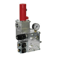
Bucher Hydraulics LRV-1 Installation And Startup Manual (86 pages)
Lift Control Valve
Brand:
Bucher Hydraulics
| Category:
Control Unit
| Size: 13.55 MB
Table of Contents
Table of Contents
3
General, Product Description
5
Target Group
5
Supplementary Documents
5
Specialist Terms
5
Important Notes
6
Subassemblies
6
Intended Use
6
Conformity
7
Product Identification
8
Nameplate
8
Test Number
8
Model Code
9
LRV-1 Lift Control Valve
10
Simplified Hydraulic-Electrical Diagram
11
Electrical Connection Diagram
12
Factory Settings
13
Description of Function
13
Technical Data
16
Pressure Drop
18
DELCON Electronic Card
20
Factory Settings
20
Description of Function
21
Technical Data
22
Travel and Switching Diagram for Normal Travel Distance
23
Travel and Switching Diagram for Short Travel Distances
24
NTA-2 Power Supply Unit
25
Description
25
Technical Data
28
Terminal Assignments
29
IWK-1 Feedback Cable
31
Surroundings
31
Emissions
31
Safety Instructions
32
Operating Controls and Indicators
33
Emergency-Lowering Valve (en 81.2 Art. 12.9)
34
Display of the Operating Status
35
Miniterminal
35
Handterminal
38
Password
39
Windelta32 - PC Program
43
Installation and Commissioning
44
Installation
44
Assembly
44
Hose or Pipe
44
Power Supply Unit
45
Wiring the Power Supply Unit
46
Electrical Emergency-Lowering 2 X 24 VDC
47
Electrical Emergency-Lowering 1 X 12 or 1 X 24 VDC (Option)
48
Commissioning/Settings
49
Checking the Test Numbers
49
Checking the Minimum Static Pressure
49
Bypass Pressure Setting
50
Setting of the Max. Operating Pressure (en 81-2, Art. 12.5.3)
53
The Demand/Feedback Response Difference, SIU-1
54
Speed-Monitoring in the Unlocking Zone of the Door SIU-4
54
The Inspection-Travel Speed Setting
54
Positioning the Shaft Switches for the Deceleration Distance
55
Setting the Mechanical Zero Point
56
4.3.10 Pilot Filters
57
4.3.11 Pipe Rupture Valve Test
59
Operation
63
Parameterisation with Handterminal
63
Parameterisation with Miniterminal
64
Overview Travel Curve Parameters
64
Overview Control Parameters (PID)
65
Description of Parameters
65
Demand Values Menu
65
Options Menu
67
Zero Point / Hall Sensor Menu
71
Information Menu
72
Calculating the Demand Values for Maximum Speed
73
Faults / Fault-Finding
74
Check List for Fault Correction
74
Error Messages
78
Warnings
80
Informations
81
Maintenance
82
Maintenance Schedule
82
Hydraulic Fluids
83
Jerky Movement at Low Speed
83
Mineral Oils
83
Tested and Approved Hydraulic Fluids with Biodegradable Characteristics
84
Useful Service Life
85
Installation Guide for down Pilot Valve
86
Advertisement
Advertisement
Related Products
Bucher Hydraulics NS 32
Bucher Hydraulics VF-iValve VF-i250 Series
Bucher Hydraulics VF-iValve VF-i500 Series
Bucher Hydraulics Categories
Control Unit
Industrial Equipment
Amplifier
More Bucher Hydraulics Manuals
Login
Sign In
OR
Sign in with Facebook
Sign in with Google
Upload manual
Upload from disk
Upload from URL