Sign In
Upload
Manuals
Brands
BSA Manuals
Motorcycle
M20
BSA M20 Manuals
Manuals and User Guides for BSA M20. We have
1
BSA M20 manual available for free PDF download: Maintenance Manual And Instruction Book
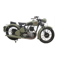
BSA M20 Maintenance Manual And Instruction Book (53 pages)
500 c.c. s.v.
Brand:
BSA
| Category:
Motorcycle
| Size: 2.74 MB
Table of Contents
Index
2
Useful Data
4
The Lubrication System
6
Lubrication Chart
7
Lubrication Chart
8
The Engine - Exploded View
9
Top Half of Engine (Exploded View)
9
Crankcase Half of Engine (Exploded View)
10
Engine Adjustments
11
Oil Pressure Valves
11
Exhaust Valve Lifter
11
Tappet Adjustment
11
Ignition Timing
12
Instructions for Setting Tappets
12
Magneto Pinion Extractor
12
Carburetor
13
Sparking Plug
13
Needle Position
13
Throttle Stop
13
Engine Dismantling for Decarbonising
14
Removing Cylinder Head
14
Removing Cylinder Barrel
14
Removing the Valves
14
Removing Engine from the Frame and Complete Dismantling
15
Piston and Rings
15
Removing Chaincase
15
Removing Clutch
16
Dismantling the Engine
16
Removing Magdyno Pinion
16
Angle Bracket for Mounting Engine
16
Oil Pump Spindle Locking Plunger
17
Ballrace Extraction (Gearside)
17
Cam Pinion Spindle Extractor
18
Two Scoops Diametrically Opposite, Ground after Liner Is Pressed in
18
Re-Assembling the Engine
19
Flywheels
19
Checking Flywheel Alignment
19
Method of Correcting Flywheels out of Alignment
19
Crankcase
20
Timing Gears
20
Valve Timing Marks
20
Cylinder and Piston
21
Cylinder Head Bolts
21
Assembly of Chaincase and Footrest
21
Transmission
23
Clutch Adjustment
23
Front/Rear Chain Adjustment
23
Dismantling and Re-Assembling the Clutch
24
Wheel Alignment Gauge
24
Clutch Extractor Tool
24
Re-Assembly of the Clutch
25
Clutch Assembly Tool
25
Section through Clutch
25
Removal of Gearbox
26
Dismantling the Gearbox
26
Gearbox Fixture
26
Pinion Sleeve Removal Tool
26
Dismantling the Gearchange Mechanism
27
Re-Assembly of the Gearbox and Gearchange Mechanism
27
Gear Train
27
Selector Quadrant
27
Re-Assembly of the Gearchange
28
Special Instructions for the Cleaning and Lubrication of Hubs
30
Replacement of the Gearbox
30
Adjustment, Dismantling and Re-Assembly of Hubs and Brakes
31
Rear Hub
31
Section through Rear Hubs
31
Adjustments to Steering Head and Front Forks
33
Front Hub
33
Brake Adjustment
33
Brake Relining
33
Removal and Dismantling of Front Forks and Steering Head
34
Headlamp Connections
34
Steering Head Ballrace Extractor
34
Chain Alternations and Repairs
35
How to Use the Chain Rivet Extractor
35
To Shorten a Worn Rear Chain
35
To Repair a Damaged Chain
35
How to Measure Wear in a Motor Cycle Chain
36
The Electrical Equipment
37
The Wiring System
37
Simple Wiring Diagram for Models Fitted with Ammeter
37
Simple Wiring Diagram for Models Fitted Without Ammeter
37
Wiring Diagram in Models Fitted with Ammeter
38
Wiring Diagram for Models Without Ammeter
38
Ignition (Section A)
39
Lubrication
39
Adjustment
39
Contact Breaker with Cover Removed
39
Exploded View of Components of the Slipping Clutch
40
Slipping Clutch Showing the Jig to Lock the Larger Gear
40
Exploded View of Magneto Portion of Dynamo
40
Magneto Earthing Brush
41
Method of Removing Outer Journals of Bearings
41
Tool for Fitting Outer Journals of Bearings
42
Magneto Contact Breaker End Showing Fitting of Cam, Timing Control and Shims
42
Contact Breaker Assembly
42
Method of Checking Clutch Setting
42
Charging
43
Dynamo Type E3HM
43
Dynamo Testing in Position
43
Dynamo with Cover Band Removed to Show Brush Gear
43
Exploded View of Dynamo
44
Dynamo – Dismantling
44
Dynamo Brushes
44
Dynamo - Commutator
44
Dynamo – Field Coil
45
Dynamo - Armature
45
Dynamo – Bearings
45
Method of Undercutting Mica
45
Dynamo – Re-Assembly
46
Cut-Out and Regulator Unit, Type MCR1
46
Regulator – Testing in Position
46
Removing the Ballrace
46
Regulator – Cleaning the Contacts
47
Regulator – Mechanical Setting
47
Cut-Out
47
Regulator Adjustment and Setting
47
Ammeter, Type CZ27
48
Battery, Type PUW7E
48
Checking Battery Condition
48
Lighting and Accessories
49
Headlamp, Type DU42
49
Removing Lamp Front and Reflector
49
Headlamp – Reflector Partially Removed
49
Horn, Type HF1235
50
Headlamp, Type du 42
50
Horn Showing Adjusting Screw
50
Headlamp, Type DU42 with Reflector Partially Removed
50
Change-Over Switch
51
Main Lighting Switch
51
Panel Containing Change-Over Switch, Removed from Headlamp
51
Tool Kit Supplied with the Machine
52
Additional Equipment
52
Advertisement
Advertisement
Related Products
BSA 1946 B31
BSA 1946 B32 Competition
BSA 1946 B32 Gold Star
BSA 1946 B33
BSA 1946 B34 Competition
BSA 1946 B34 Gold Star
BSA 1947 B31
BSA 1947 B32 Competition
BSA 1947 B32 Gold Star
BSA 1947 B33
BSA Categories
Motorcycle
Bicycle
Plumbing Product
Control Unit
Controller
More BSA Manuals
Login
Sign In
OR
Sign in with Facebook
Sign in with Google
Upload manual
Upload from disk
Upload from URL