Sign In
Upload
Manuals
Brands
Brush Bandit Manuals
Chipper
65XL
Brush Bandit 65XL Manuals
Manuals and User Guides for Brush Bandit 65XL. We have
1
Brush Bandit 65XL manual available for free PDF download: Operating & Parts Manual
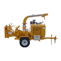
Brush Bandit 65XL Operating & Parts Manual (150 pages)
brush chipper
Brand:
Brush Bandit
| Category:
Chipper
| Size: 10 MB
Table of Contents
Chipper Components
1
Clutch Components
1
Engine Components
1
Table of Contents
2
Introduction & Warranty
3
Typical Chipper Serial Number And/Or Work Order Number Locations
7
Safety Procedures
8
Ascending or Descending Slope
13
Side Slope
13
Maximum Slope Grade
13
If Machine Is Equipped with a Self Propelled Undercarriage
13
Approximate Dimensions & Weights
14
Fuel Tank Capacity
14
Hydraulic Tank Capacity
14
Equipment Specifications
14
Decals
16
Decal Locations - Model 65
17
Decal Locations - Model 95
21
Autofeed System
28
Part Numbers for Autofeed Digital Tach Hour Meters
28
Autofeed Options
28
Autofeed Terminology
29
Trouble Shooting Guide
30
Approximate Digital Autofeed Settings
31
Correct Operation of Feed Control Handle
32
Adjusting Tension for Control Handle Pivot and Last Chance Cable Pull
32
Controls
32
Models 65/95 Basic Location of Controls and Adjustments
33
Model 65/95 Chip Box Basic Location of Controls and Adjustments
34
Yoke Lift Control - Optional
35
Selector Valve Control - Optional
35
Feedwheel Control Bar
35
Control Operating Procedures
35
Winch Operating Procedures
36
Operating Procedure
36
Chipper Hood Engine Disable Plug Operation
37
Spring Lock for Hood Pin Operation
38
Ignition Switch
39
On/Off Switch - Push Button Start
39
Ignition Switch with Preheat
39
Choke Adjustment
39
Transportation Procedures
40
Loading & Unloading Self-Propelled Machines
41
Daily Start up & Maintenance
42
Maintenance Section
42
Check Chipper Disc Assembly
43
Check Chipper Disc/Drum to Turn
43
Check Hydraulic Oil Level
43
Grease Yoke Pivot Bearings
43
Check Air Cleaner or Precleaner
44
Check Clutch
44
Check Oil Cooler
44
Weekly Maintenance
44
3 Month Maintenance
45
Check Towing Hitch
45
Monthly Maintenance
45
Yearly Maintenance
45
Basic Wheel Torque Requirements
46
Bolt Torque Chart
46
Daily Start up & Maintenance Check List
47
3 Month Check List
48
Monthly Check List
48
Weekly Check List
48
Yearly Check List
48
Lubrication Chart
49
Lubrication Chart - Chip Box
51
Belt Tension
53
General Rules for Tensioning
53
Main Drive Belts
53
Tensioning Procedure
53
Model 65 Drive Belt Replacement
55
Installation Procedure
56
Proper Equipment Needed
56
Anvil Adjustment
57
Anvil Adjustment Procedure
58
Check the Anvil to Knife Clearance
58
Grip Tight Bearing
59
Servicing / Changing Feedwheel Bearing
59
Set Screw Bearing
59
Procedure for Unplugging Your Chipper
60
Steps to Follow When Unplugging Your Chipper
60
Paint Care
61
Recommended Brake Adjustment Procedure Per Axle Manufacturer
62
Tire Wear Diagnostic Chart
62
Hydraulic Fluid Requirements
63
Hydraulic Section
63
Typical Hydraulic Flows and Rpm Settings
65
Typical Hydraulic Relief Pressure Settings
65
Hydraulic Components
67
Hydraulic Pump
67
Hydraulic Tank
67
The Bandit Hydraulic System
67
Poppit Valve
69
Procedure 1 for Models 65/95 with no Options
69
Relief Spring
69
Valve Seat
69
Checking and Adjusting Relief Valve Pressure
70
Procedure 2 for Models 65/95 with Options
71
Hydraulic Pressure Adjustment Procedure Options
72
Procedure 3 for Models 65/95 with Options
72
Models 65/95 Procedure
73
Procedure for Checking Optional Hydraulic Components
73
Hydraulic System Trouble Shooting
74
Correcting Hydraulic Problems
75
Hydraulic Motor Check out
76
Hydraulic Motor Check out for Machines with Live Hydraulics
76
Hydraulic Pump Check out
77
Hydraulic Pump Check out Without Using a Flow Meter
77
Hydraulic Pump Check out Using a Flow Meter
78
Control Valve Detent Assembly and O-Ring Replacement
79
Tools Required
79
Models 65/95
80
Model 65 with Dual Feedwheels
81
Chipper Section
83
Trouble Shooting Chipper Problems
83
Dull Knives Cause
84
Knife Grinding and Filing
84
Knife Changing Procedure
85
Chip Box Turntable Bearing
86
Lubrication & Coolant
86
Yoke Pivot Bearings
86
“Bandit Lever Throttle Cable
86
6 Wire Main Cable Color Code
87
6 Wire Main Cable Color Code (Old Style)
87
Electrical Section
87
Old Style
87
Typical Electrical Wiring Diagrams
87
Replacement Parts Section
88
Infeed Hopper Components
89
Infeed Hopper Components
91
Dual Feedwheel Components
93
Model 65 Dual Feedwheel
93
Chipper Components
95
Chipper Knife & Hardware
99
Part Numbers for Model 65 Knives
99
Part Numbers for Model 95 Knives
99
Part Numbers for Miscellaneous Knife Parts
99
Anvil & Hardware
100
Discharge Components
101
Standard Discharge
101
Discharge Assemblies
101
Hand Crank Adj. Height Discharge
102
Hand Crank Swivel Discharge
103
Model 95 - Hydraulic Swivel Discharge
105
Model 95 - Discharge with Hydraulic Flipper
106
Model 95 - Telescopic Discharge
107
Typical Models 65/95 Hydraulic Schematic
108
Hydraulic Components
108
Hydraulic Schematic
109
Relief Block
115
“Auto Feed Plus” System
115
Hose Clamp
117
Hose Guard
117
Flow Divider
117
Typical Spring Loaded Control Valve
119
Typical Feedwheel Control Valves
119
Typical Spring Loaded Control Valve Components
120
Typical Feedwheel Control Valve Components
120
Control Valves
120
Frame & Accessory Components
121
Model 65 Tanks & Components
127
Fuel & Hydraulic Tank Components
127
Model 95 Tanks & Components
129
Prior Turntable (Pre 1/07)
131
Prior Light Mounts (Pre 1/07)
131
Chip Box & Accessory Components
131
Optional Components
135
Pto Components
138
Service Record
149
Advertisement
Advertisement
Related Products
Brush Bandit 65XP
Brush Bandit 65A
Brush Bandit 65AW
Brush Bandit 150
Brush Bandit 1850
Brush Bandit 200
Brush Bandit 280
Brush Bandit 280HD
Brush Bandit 75
Brush Bandit 90
Brush Bandit Categories
Chipper
Grinder
Brush Cutter
More Brush Bandit Manuals
Login
Sign In
OR
Sign in with Facebook
Sign in with Google
Upload manual
Upload from disk
Upload from URL