Sign In
Upload
Manuals
Brands
Bruker BioSpin Manuals
Amplifier
BLAH2000-I E C
Bruker BioSpin BLAH2000-I E C Manuals
Manuals and User Guides for Bruker BioSpin BLAH2000-I E C. We have
1
Bruker BioSpin BLAH2000-I E C manual available for free PDF download: Operating & Service Manual
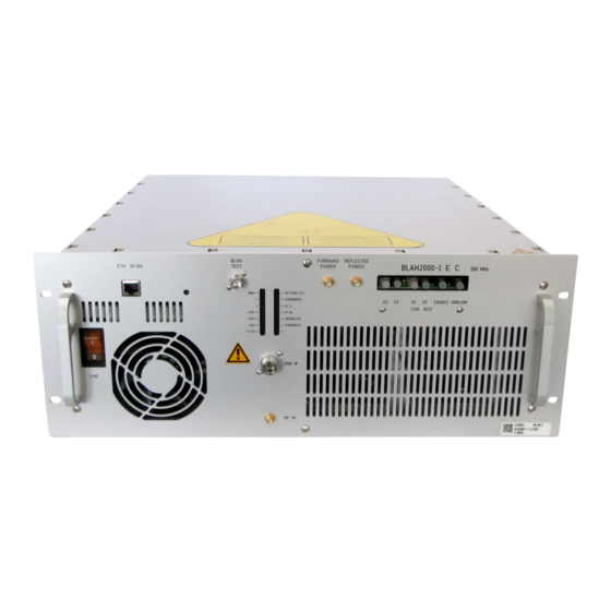
Bruker BioSpin BLAH2000-I E C Operating & Service Manual (48 pages)
Amplifier 300MHz
Brand:
Bruker BioSpin
| Category:
Amplifier
| Size: 2 MB
Table of Contents
Table of Contents
3
Contents
3
Table of Contents
3
1 General Information
5
Introduction
5
2 Safety
7
Labels
7
Figure 2.1. Identifying Plate
7
Identifying Plate
7
Figure 2.2. Manufacturer's Name Plate
8
Manufacturer's Name Plate
8
Safety Labels and Symbols
9
Operating Instruction
9
Risk of Danger
9
Warning Signs
9
3 Installation
11
Initial Inspection
11
Claim for Damage
11
Mechanical Check
11
Reshipment and Repackaging Requirements
11
Environment Requirements
12
Installation Requirements
12
Bench Operation
12
Power Requirements
12
System Check
12
Initial Turn on Procedure
13
4 Operation
15
Front Panel Description
15
Indicators
15
Table 4.1. Indicators Assignment
15
Coaxial Connectors
16
Ethernet 10/100 Interface Connector
16
Table 4.2. Coaxial Connectors Assignment
16
Table 4.3. RJ45 Pin Assignment
16
CAN Bus Interface Connectors
17
Device Front View
17
Figure 4.1. BLAH2000-I E C Amplifier 300Mhz Front Panel Design
17
Table 4.4. CAN Bus Connectors Assignment
17
Rear Panel Description
18
Device Rear View
18
Figure 4.2. BLAH2000-I E C Amplifier 300Mhz Rear Panel Design
18
Figure 4.3. BLAH2000-I E C Amplifier 300Mhz Rear Panel View
19
5 Technical Description
21
System Overview
21
Figure 5.1. BLAH2000-I E C System Block Diagram
22
Figure 5.2. Driver Block Diagram
23
Theory of Operation
24
RF 4 Ways Combiner
24
RF 4 Ways Splitter
24
RF Driver
24
RF Path
24
RF Power Amplifier
24
BLA Control Board
25
RF Coupler
25
BIS Board
26
CAN 1 in (RX U3) / out (TX U2)
26
CAN 2 in (RX U5) / out (TX U4)
26
CAN BUS Interface
26
Enable
26
Status Led Board
26
Unblank
26
6 Servicing the BLA
27
Accessing the BLA Amplifier
27
Sub Toolbar Information
28
Device Information (Default)
28
Figure 6.1. Device Information
28
Amplifier Status
29
Figure 6.2. Amplifier Status
29
Sub Toolbar Advanced Operations
30
Device Information (Advanced)
30
Figure 6.3. Device Information
30
Amplifier Limitations
31
Figure 6.4. Amplifier Limitations
31
Change Limits
32
Figure 6.5. Change Limits
32
Figure 6.6. Routing Information and Setting
33
Routing Information and Setting
33
Sub Toolbar Maintenance
34
Device Information (Maintenance)
34
Figure 6.7. Device Information
34
Figure 6.8. Perform Self Test and Report
35
Self-Test & Software Reset
35
Figure 6.9. Perform Software Reset and Report
36
Figure 6.10.Firmware Update
37
Firmware Update
37
BIS Content
38
Figure 6.11.BIS Content
38
7 Specifications
39
Common Characteristics
39
Table 7.1. Amplifier Common Characteristics
39
General Specifications
40
Channel 2000W Output
40
Table 7.2. Channel 2000W Output Specifications
40
8 Service Information and Maintenance
41
Preventive Maintenance of the RF Module on BLA-Type Amplifiers
41
Operation
41
Figure 8.1. Fan Supplies and Status Connections
42
Figure 8.2. Push Fan Assembly
42
Figures
43
Tables
45
Advertisement
Advertisement
Related Products
Bruker BioSpin BCU-Xtreme
Bruker BioSpin BEST
Bruker BioSpin NMR BVT3200
Bruker BioSpin Categories
Measuring Instruments
Laboratory Equipment
Amplifier
Barcode Reader
Controller
More Bruker BioSpin Manuals
Login
Sign In
OR
Sign in with Facebook
Sign in with Google
Upload manual
Upload from disk
Upload from URL