Sign In
Upload
Manuals
Brands
Borg Warner Manuals
Microphone system
72C
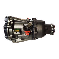
Borg Warner 72C Manuals
Manuals and User Guides for Borg Warner 72C. We have
1
Borg Warner 72C manual available for free PDF download: Service Manual
Borg Warner 72C Service Manual (84 pages)
Velvet Drive Marine Transmission
Brand:
Borg Warner
| Category:
Microphone system
| Size: 2 MB
Table of Contents
Table of Contents
4
List of Figures
5
List of Table
5
Description
6
Theory of Operation
6
Technical Specifications
6
Typical Installation
7
Forward Power Flow
7
Reverse Power Flow
7
Hydraulic Circuit Schematic (Model C Direct-Drive Shown)
8
Scheduled Inspection
9
Maintenance
11
General
11
Lubrication
11
Troubleshooting
13
Guidelines
13
Overhaul
17
Disassembly
17
Cleaning
17
Repair
17
Assembly
18
Bushing Installation
18
Case Assembly
19
Oil Shield Assembly
19
Pinion Carrier Assembly
20
Forward Clutch Pack Arrangement
20
Forward Clutch Pack Assembly
21
Snap Ring Installation
21
O-Ring Installation
21
Clutch Rings Installation
22
Piston Installation
22
Clutch Spring Assembly
22
Forward Clutch Cylinder Installation
23
Compressing Clutch Pack
23
Snap Ring Selection
24
Snap Ring Assembly
24
Sealing Ring Installation
24
Bearing Installation
25
Trurswasher Assembly
25
Clutch and Drive Gear Installation
26
Thrustwater Installation
26
Friction Plate Installation
26
Spring and Dowel Pin Installation
27
Reverse Clutch Pack Installation
27
Pressure Plate Installation
27
Sealing Ring Assembly
28
Reverse Clutch Piston Assembly
28
Adapter Installation
29
Oil Seal Installation
29
Pump Driven Gear Assembly
29
Pump Gasket Installation
30
Pump Assembly Installation
30
Valve Assebmly
30
Valve Assembly Installation
31
Switch Cam Installation
31
Valve Cover Installation
31
Shift Level Assembly
32
Bearing Retainer
32
Coupling Installation
32
Dipstick Installation
33
Shift Cable Adjustment
33
Oil to Cooler Outlet
33
71C and 72C Transmission Assembly-Current Production
34
Model Chart 71C and 72C Transmissions
40
Specifications
41
Bolt and Fastener Torques (Non-Lubricated)
41
Spring Dimensions
41
Test Pressures
42
1.523:1 Reduction Units
43
Bearing Cone Assembly
44
Bearing Cup Assembly
44
Spacer and Bearing Cone Assembly
44
Oil Seal Assembly
45
Coupling Assembly
45
Sun Gear Assembly
46
Sun Gear Installation
46
Pinion Carrier Installation
46
Input Gear Assembly
47
Reduction Unit Adapter Assembly
47
Front Adapter Gasket Installation
47
Reduction Unit Adapter Installation
48
Rear Adapter Gasket Installation
48
Reduction Housing Installation
48
1.523:1 Reduction Units-Current Production
49
1.523:1 Reduction Units-Early Production
51
1.88:1 and 1.91:1 Reduction Units
52
Main Shaft Assembly
53
Lube Oil Strainer Installation
56
Pinion Carrier Gasket Installation
56
1.88:1 and 1.91:1 Reduction Units-Current Production View
58
1.88:1 and 1.91:1 Reduction Units-Current Production
60
1.91:1 Reduction Units-Early Production
63
2.57:1 and 2.91:1 Reduction Units
64
Oil Baffle Installation
65
Stationary Gear Plate Assembly
67
2.57:1 and 2.91:1 Reduction Units-Current Production
70
2.57:1 and 2.91:1 Reduction Units-Early Production
73
2.10:1 Reduction Unit
74
Output Shaft Assembly
75
Thrustwasher Installation
78
Pinion Cage Installation
78
2.10:1 Reduction Units-Current Production
80
2.10:1 Reduction Units-Early Production
83
Advertisement
Advertisement
Related Products
Borg Warner 71C
Borg Warner Categories
Microphone system
Controller
DC Drives
More Borg Warner Manuals
Login
Sign In
OR
Sign in with Facebook
Sign in with Google
Upload manual
Upload from disk
Upload from URL