Sign In
Upload
Manuals
Brands
Belden Manuals
Control Panel
Grass Valley Standard
Belden Grass Valley Standard Panel Manuals
Manuals and User Guides for Belden Grass Valley Standard Panel. We have
1
Belden Grass Valley Standard Panel manual available for free PDF download: Installation & Service Manual
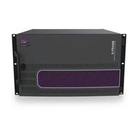
Belden Grass Valley Standard Installation & Service Manual (431 pages)
Video Production Center For K-Frame Series
Brand:
Belden
| Category:
Control Panel
| Size: 49 MB
Table of Contents
FCC Compliance
2
Copyright and Trademark Notice
2
Safety and EMC Standards
12
Safety Standards
12
EMC Standards
13
EMC Performance of Cables and Connectors
13
Table of Contents
15
Introduction
27
Overview
27
Features
27
General
27
K-Frame Standard Frame
28
K-Frame Compact Frame
29
K-Frame Compact S-Series Frame
29
K-Frame V-Series Frame
29
GV K-Frame X Standard Frame
30
Kayenne Control Surface
30
Flat or Curved Control Panel Orientation
31
Control Panel Stripes
32
Touch Screen Menu Panel
32
Menu Application
32
Basic Single Suite Kayenne Panel System
33
Multiple Suite Kayenne Panel System
33
Karrera Control Surface
34
Touch Screen Menu Panel Option
35
Karrera K-Frame System Examples
36
GV Korona Control Surfaces
37
Basic Single Suite GV Korona Panel System Example
38
Multiple Suites and Control Surfaces Example
38
Soft Panel (KSP) Option
40
Menu Application
40
Supported Control Protocols
41
Frame Installation
43
Overview
43
Weight Distribution
43
Cooling Requirements
43
Power Connections
43
15-RU (GV K-Frame X) Video Processor Dimensions
44
15RU Video Processor Installation and Airflow
46
15RU Video Processor Views
47
15-RU Power Supply Views
50
15-RU Power Supply Frame Rack Installation and Airflow
51
15-RU Power Supply Cooling
52
15-RU Power Supply AC Requirements
53
Supplied Power Cables for 15-RU
53
About 15-RU High Line (208V-240V) Versus Low Line (120V) Operations
53
About Low Line (120V) Operational Considerations
54
13-RU Video Processor Dimensions
55
13RU Video Processor Installation and Airflow
57
13RU Video Processor Views
57
6-RU Video Processor Dimensions
60
6RU Video Processor Installation and Airflow
62
6RU Compact S-Series Front View with Doors Removed
62
6RU Compact Front Views with Doors Removed
63
6RU Video Processor Rear View
64
K-Frame Controller Connections
64
3RU Video Processor Dimensions
65
3RU Video Processor Installation and Airflow
67
3RU Front Views with Door Removed
67
K-Frame V-Series Controller Connections and Status Indicators
68
K-Frame V-Series Video Processor Rear View
68
K-Frame 13RU Power Supply Views
70
K-Frame 13RU Power Supply Frame Rack Installation and Airflow
71
K-Frame 13RU Power Supply Cooling
72
K-Frame 13RU Power Supply AC Requirements
73
Supplied Power Cables for 13RU K-Frame
73
About Low Line (120V) Operational Considerations
73
About High Line (208V-240V) Verses Low Line (120V) Operations
74
K-Frame Compact Power Supply AC Requirements
74
About Low Line (120V) Operational Considerations
74
About High Line (208V-240V) Verses Low Line (120V) Operations
75
Replacing Compact Power Supplies
75
K-Frame Video Processor Door Removal Clearance
76
Control Surface Installation
77
Control Surfaces
77
Kayenne Control Surfaces
77
Control Panel and Support Structure Assembly
77
Control Panel Variations
77
Control Panel Cooling
78
Truck and High Vibration Environment Considerations
78
4-M/E 35 Control Panel, Curved Assembly
79
4-M/E 35 Control Panel, Flat Assembly
79
4-M/E 25 Control Panel
83
3-M/E 35 Control Panel, Curved Assembly
84
3-M/E 35 Control Panel, Flat Assembly
87
3-M/E 25 Control Panel
89
2-M/E 35 Control Panel, Curved Assembly
89
2-M/E 35 Control Panel, Flat Assembly with Local Aux
92
2-M/E 35 Control Panel, Flat Without Local Aux
94
2-M/E 25 Control Panel
95
1-M/E 15 Control Panel
96
Separately Mounted Local Aux Stripe (35 & 25 Models)
97
Control Panel Stripe-PCU Connections
97
Touch Screen Menu Panel Installation
98
Karrera Control Surface
101
3-M/E Karrera Control Panel Installation
101
2-M/E Compact Karrera Control Panel Installation
104
PC Requirements
106
Macintosh Computer Operation
106
Hardware Installation
106
Menu on User PC Software Installation
106
User PC Configuration
107
Optional Touch Screen Menu Panel Installation
107
Menu Panel Dimensions
108
Menu Panel Connectors
109
Menu Panel Cooling
109
Fanless PC Dimensions and Connectors
110
Menu Panel Articulated Arm Installation
111
Menu Panel Hardware Installation with Articulated Arm
112
Wall Mounting Without Articulated Arm
112
Optional Local Aux Panel Installation
113
Local Aux 25 Panel Dimensions
114
GV Korona Control Surfaces
118
3-M/E GV Korona Control Panel Dimensions
118
2-M/E GV Korona Control Panel Dimensions
121
2-M/E GV Korona Control Panel Cutout Dimensions
123
1-M/E GV Korona Control Panel Dimensions
124
1-M/E GV Korona Control Panel Cutout Dimensions
126
System Cabling
127
About the K-Frame System Cabling Section
127
System Cabling Overview
127
Ethernet Tally Verses Serial Tally
127
Suites and Control Surfaces
127
Network Cabling
127
Ethernet Switch
128
Customer Supplied Ethernet Routers and Switches
128
Factory Default Network Settings
129
System Cabling for Kayenne Control Panels
130
Kayenne Network Cabling
130
Kayenne Suites and Control Surfaces
131
Kayenne Control Panel Cabling
133
Kayenne M/E and Local Aux Stripe Connections
133
Kayenne Satellite Panel Cabling
134
Kayenne Touch Screen Menu Panels (Used with PCU)
135
System Cabling for the Karrera Control Panel
135
Karrera Suites and Control Surfaces
135
Karrera Control Panel Network Cabling
136
Optional Touch Screen Menu Panel Cabling
136
Optional Karrera Local Aux Panel Cabling
137
System Cabling for the GV Korona Control Panel
139
GV Korona Suites and Control Surfaces
139
K-Frame Video Cabling
140
10Gige IP I/O Fiber Optic Cabling
140
SDI Inputs
140
SDI Outputs
141
Reference Input
141
V-Series Reference Output
141
Supported Media Port Frame Rates
141
Clipstore Cabling
142
Clipstore Video Cabling
142
K-Frame Video Processor Frame Gpi/Relay Tally Interface
144
K-Frame GPI and Relay Tally Connections
144
GPI Inputs
145
Relay Tally/Gpi Outputs
146
GPI In, GPI Out, Relay Tally Pin Assignments
148
GV K-Frame X Video Processor Frame Gpi/Relay Tally Interface
151
GV K-Frame X GPI and Relay Tally Connections
151
GPI Inputs
151
Relay Tally/Gpi Outputs
152
GPI In, GPI Out, Relay Tally Pin Assignments
154
RS-422/485 Port Pin Assignments
158
RS-232 Port Pin Assignments
159
K-Frame 10 Gig E IP/IO Fiber Optic Cabling
159
Remote Aux Panels
161
GV-RAP-100 and GV-RAP-200 Remote Aux Panels
161
Basic Configuration
163
Introduction
163
Configuration Steps
163
Configuration Data
163
Configuration Basic Categories
164
GV Switcher Menu Application
164
Menu Top Line
165
Data Pads and Touch Buttons
165
Data Pads and Soft Knobs
166
Menu Selection
166
Power up and Initialize the System
166
Power and Initialization Indications
167
Menu Application Initialization
167
Default System Communications
167
Establishing Menu to Frame Communication
167
Connecting the Menu Application to a Frame
168
About Network Configuration
168
IP Address Background Information
168
Gateway IP Addresses
169
Default IP Addresses on Isolated Network
169
Connecting to an Existing Network
169
Setting Ips with the Switcher Installer Program
169
K-Frame System Names
170
Set IP Procedure Using the K-Frame Installer Program
171
Other K-Frame Switcher Installer Program Functions
172
Set the Ips Using Device Web Pages
173
Set the IP Video Configuration for SFP Gateway and Subnet Masks
174
Changing the Image Store IP Address
174
Changing Control Panel IP Addresses
174
Changing the Kayenne or Karrera Menu Panel IP Address
175
32-Crosspoint Remote Aux Panel IP Address
175
Restoring the Default IP Address
177
GV-RAP-100 and GV-RAP-200 Remote Aux Panels
178
Install Remote Aux Panel Software
179
Configure the Remote Aux Panel System
179
Configure the Remote Aux Panel Network
179
Connect the Remote Aux Panel to the Switcher IP Network
180
Delegate Control of a Switcher Aux Bus to the Remote Aux Panel
180
Map Switcher Sources to Remote Aux Bus Buttons
180
About S25/S50 Remote Aux Panel Upgrade
181
Switcher Remote Aux Button Functionality
181
Install S25/S50 Remote Aux Panel Software
182
Configure the Remote Aux Panel System
182
Configure the Remote Aux Panel Network
182
Connect the Remote Aux Panel to the Switcher IP Network
183
Delegate Control of a Switcher Aux Bus to the Remote Aux Panel
183
Map Switcher Sources to Remote Aux Bus Buttons
183
About K-Frame IP I/O
184
Standard, Compact, and S-Series IP I/O
184
GV K-Frame X and V-Series IP I/O
185
GV K-Frame X/V-Series Video I/O IP Config Bulk Configuration
190
About 4K TICO Compression Formats in the IP I/O Config Menu
193
About IP I/O Address and Port Configuration
193
Configure the IP I/O IP Address and Ports
194
Configure ST 2110-40 Ancillary
196
GV K-Frame X and V-Series IP/IO Configuration
197
Hot Swappable IP I/O Boards and Sfps
199
Troubleshooting
199
About IP Audio, Ancillary, and Redundancy
204
Video I/O IP Setup and Configuration Overview
205
Configure the Port Config Sfps
205
Configure System Inputs/Outputs
205
Configure System Input or Output Sfps in Bulk from the Menu
206
GV K-Frame X/V-Series IP SFP Statistics Web Access
212
Setting the RTP Payload Type for GV K-Frame X and V-Series
213
Registering K-Frame System Nodes
214
Kayenne and Karrera Menu Panel Registration
214
K-Frame Control Panel Registration
215
Remote Aux Panel Registration
215
Control Panel Brightness Adjustment
216
Engineering Setups
217
Source Definition Inputs
217
Change Direct Source Definition
219
Source Naming Background Information
219
Engineering Names, Eng Ids, and Logical Ids
219
Alternative Source Names
220
Source Patch Feature
222
Output Assignments
223
Default Output Assignments
224
Change Output Assignments
224
Configuring Aux Buses
225
M/E Viewer
228
Switcher Relay Tally Configuration
229
About Relay Tally Systems
229
Switcher Relay Tally Calculator Menus
230
Creating an on Air Relay Tally Calculator Using M/Es or PGM/PST
231
Create an on Air Relay Tally Calculator Using Aux Buses
232
Creating a Look Ahead Relay Tally Calculator
232
Creating a Bus Relay Tally Calculator
233
Relay Assign Menu
234
Assign Sources to Tally Relays
235
About MV Green Relay Tally Calculations for Multiviewer On-Air and Green
236
Configure MV Green Relay Tally for Look Ahead Preview
236
Ethernet Tally Configuration
236
Configure the On-Air Tally Program M/E
237
Configure the GV Switcher Ethernet Tally System Interface
237
Set Source Names with External Ethernet Tally
238
Clipstore Configuration
239
Summit/Solo Software Version
239
Setting the Summit IP Address
239
Install the Clipstore License
239
Configure Clipstore as a Node
240
Configure Source Definitions
241
Configure Outputs
242
Acquire and Assign CS Channels in Another Suite
242
Clipstore Config Menu
242
Assigning Clipstore Channel Resources to a Suite
244
Set the Summit/Solo IP Address
244
Configure the Remote Desktop Connection
244
Clipstore Hosts File Update
248
Update Hosts File for Windows 7 or Newer
248
Update Hosts File for Windows XP
249
4K Frame Operating Mode Configuration
250
System Requirements
250
4K Physical M/E to Logical M/E Acquisitions
250
Configure a 4K Frame Operating Mode Video Setting
250
About Releasing Resources in 4K Mode
251
Configure a 4K Source Definition (Video Inputs)
251
Configure a 4K Key Source Definition (Key Inputs)
251
Configure a 4K Output
251
Camera Control with Ethernet Tally Configuration
252
Configure Node Settings
252
Configure Source Definitions
253
Acquire Resources
255
Switcher Ethernet Camera Tally
256
Tally Calc Menus
257
Color Assign Menu
257
User Setups
258
Configuration File Save and Load
258
File Storage Organization
260
K-Frame Drive Access
260
Eng Setup File Operations
260
Save Eng Setup Files
261
Load Eng Setup Files
261
Multiple Suite Resource Sharing
262
Collaborative Resource Sharing
262
Independent Resource Sharing
262
Suites
263
Control Surface
263
Logical Aux Buses
264
Remote Aux Panels
264
External Control Points
264
Setting up Resource Sharing
264
Prepare Worksheet
265
About the Frame Suite Nodes and ID Menu
265
Configure Control Surfaces
266
Kayenne (Only) PCU Configuration
267
Define Default Multi-Suite Engineering Resources
269
Acquire Resources in Suites
270
Save Default Multi-Suite Engineering Setup File
272
Define and Save Default Suite Prefs
272
Define and Save Default Panel Prefs
272
Multi-Suite Independent Operation
272
Engineering Login
272
Matchdef and Setdef (Standard/Compact/S-Series)
273
Matchdef Input Conversion
274
Setdef Output Conversion
275
About GV K-Frame X and V-Series Matchdef and Setdef Conversion
276
Supported Matchdef Input Conversion
276
Supported Setdef Output Conversion
278
K-Frame GV K-Frame X and V-Series Conversion Menus
280
Mod I/O and Video I/O Conversion Pane
281
Mod I/O and Video I/O Matchdef Conversion Configuration Pane
282
Mod I/O and Video I/O Setdef Conversion Configuration Pane
283
Standard Definition
284
About 4K Conversion (GV K-Frame X and V-Series)
285
GV K-Frame X and V-Series Media Port Menus
287
Configure Matchdef for the Video I/O Output Format Conversion
287
Match Sync
288
About the GV K-Frame X 12G SDI GB (Gearbox) Board
289
Input Formatting
289
About Timing
290
Output Formatting
290
Matchsync
290
Supported Gearbox Format and Frame Operating Mode Compatibility
291
Video I/O Menu Updates
292
Gearbox Bulk Configuration Menu
296
Apply I/O Bulk Config Settings
298
Saving/Loading I/O Config Parameters
301
Video Settings
302
1080Sf EZ 4K Frame Operating Modes
302
Reference Sync Selection
303
About GV K-Frame X PTP Reference
303
Configuring the PTP Master
304
SFP Redundancy
305
SFP Input Status
305
Port Configuration
305
Frame Operating Mode
306
ME Blanking Settings
306
About Switcher System Timing
307
K-Frame Standard, Compact, and S-Series System Video Timing
307
Timing Analyzer
309
Time Zones and the Autotiming Window
309
GV K-Frame X and V-Series Switcher System Timing
311
Correcting an Out-Of-Time Stream
316
Other Settings
316
Nominal IP Stream Throughput
319
IP Timing Troubleshooting
319
Node Settings
319
Frame Suite Nodes & ID Menu
319
Mapping Logical Remote Aux Panels
320
Remote Aux Button Mapping
320
About the Status Menu
321
Acquire Resources
321
General Procedure to Acquire Resources
321
Acquire Multiviewer Resources with a Standard Frame
322
Acquire Multiviewer Resources with a Compact (Six-Keyer) Frame
324
Acquire Multiviewer Resources with a Compact S-Series (Four-Keyer) Frame
325
External Interfaces
327
Introduction
327
General External Device Interfacing
327
Ports & Devices
328
Pbus Ports
328
Copy Trigger Names
329
GPI Outputs
330
Pbus and GPI Enables
331
External Devices
333
VDCP Ethernet
334
VDCP on Ethernet Configuration
334
Device Definition
335
Create an External Device Definition
336
Configure an External Device for Xpression Control
337
Ethernet Tally Ports
337
Configure Ethernet Tally Ports
338
About Editor Ports
338
Router Interface
341
Router Source Name Changes (at the Router) and GV Switcher Updates
341
Features
342
Control Interface Cabling
342
Video Interface Cabling
342
External Routing System Configuration
342
Setting IP Addresses
342
Primary and Secondary Router Communications
343
Define Routed Source Definitions
344
User Setups
345
Maintenance
347
Introduction
347
Servicing Precautions
347
Grass Valley Web Site
347
Grass Valley Customer Support FAQ Database
347
Video Processor Frame Reset Procedure
347
Panel Control Unit (PCU) Reset (Kayenne Only)
348
Kayenne Control Panel Adjustments
348
Kayenne Lever Arm Calibration
348
Calibrating the Joystick
349
M/E Stripe Mapping
350
Karrera Control Panel Adjustments
351
Lever Arm Calibration
351
Karrera Joystick Calibration
353
Karrera Panel Saver Time Adjustment
355
Kayenne and Karrera Touchscreen Calibration
355
GV Korona Control Panel Adjustments
358
GV Korona Lever Arm Calibration
358
GV Korona Joystick Calibration
360
GV Korona Panel Saver Time Adjustment
361
Software Installation
362
Software Option Authorization
362
Authorization Codes
362
Expiration Dates
363
Authorization Procedure
363
Control Panel Web Pages
365
Control Panel NV Memory
365
Clear Control Panel NV Memory Procedure
365
Control Panel IP Information
366
Kayenne/Karrera Menu Panel IP Information
366
Video Processor Frame Maintenance
366
Video Processor Frame NV Memory
366
Clear NV RAM for Control Panel and Frame
366
Restore System Files
367
Restoring Multiple Suites
367
IP Address Information
367
VP Frame Processor Board Replacement
368
Video Processor Frame Battery Replacement
368
License Information
369
Lifetime of the Internal Battery
369
IP Information
370
Kayenne/Karrera Menu Panel IP Information
370
Kayenne Control Panel System Bar Maintenance
370
Removing the Kayenne System Bar
370
Replacing the Kayenne System Bar
371
3-ME Karrera Control Panel Interior
374
2-ME Karrera Control Panel Interior
376
General Control Panel Lid Switch Board Remove and Replace
380
Source Select Switch Board Remove and Replace
380
Transition Board Remove and Replace
381
Multi-Function Board Remove and Replace
381
Diagnostics
381
Capture Software Diagnostic Data
381
Kayenne Control Panel Module Diagnostics
382
HAD FPGA Updates
384
When to Update the HAD FPGA
384
Upgrade the HAD FPGA
384
Update the HAD FPGA Using a Telnet Session
385
12.X to 14.3 Upgrade: Install IP Board ARM Software
389
PTP Mezzanine Board ARM Software Upgrade
389
Downgrade the IP Board ARM Software
391
Creating Compact Flash Cards
393
Materials Required
395
CF Card Formatting Procedure
395
Updating System Software on a New Control Panel CF Card
395
Restore Control Panel Configuration Files
395
Video Processor Frame
397
SNMP Monitoring
398
GV Korona Control Panel
398
Menu Panel Processor
398
Grass Valley Switcher Device Monitoring by SNMP
399
Control Panel
400
SNMP Licensed Configuration
400
SNMP Installation
401
SNMP Licensing
401
Video Processor Frame Traps
401
Licensing Definitions
402
SNMP Power up License Processing
402
Control Panel Traps
402
Switcher Device SNMP Configuration Procedure
403
SNMP Trap Messages
404
Appendix A Specifications
407
K-Frame Video Processor Specifications
407
Kayenne K-Frame Control Panel Specifications
410
Karrera K-Frame Control Panel Specifications
412
GV Korona Control Panel Specifications
414
Appendix B Field Replaceable Units
417
Video Processor Frames
417
Control Panels
419
Kayenne
419
Karrera
423
GV Korona
424
Appendix C Regulatory Notices
427
Certifications and Compliances
427
FCC Emission Control
427
Canadian EMC Notice of Compliance
427
EN55022 Class a Warning
427
Canadian Certified AC Adapter
427
FCC Emission Limits
428
Certification
428
DEKRA Certificate
429
Advertisement
Advertisement
Related Products
Belden Grass Valley Kayenne
Belden Grass Valley Karrera
Belden Grass Valley GV Korona
Belden grass valley G2 Series
Belden grass valley MASTERPIECE IP
Belden grass valley KULA AV
Belden Grass Valley IPVU Series
Belden Grass Valley IPVU-UHD
Belden Grass Valley K-Frame
Belden Grass Valley Kaleido-X
Belden Categories
Switch
Monitor
Control Unit
Control Panel
Media Converter
More Belden Manuals
Login
Sign In
OR
Sign in with Facebook
Sign in with Google
Upload manual
Upload from disk
Upload from URL