Sign In
Upload
Manuals
Brands
BECS Manuals
Controller
BECSys3 115VAC
BECS BECSys3 115VAC Manuals
Manuals and User Guides for BECS BECSys3 115VAC. We have
2
BECS BECSys3 115VAC manuals available for free PDF download: Installation And Technical Manual, Operation And Maintenance Manual
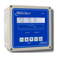
BECS BECSys3 115VAC Installation And Technical Manual (36 pages)
Brand:
BECS
| Category:
Controller
| Size: 2 MB
Table of Contents
Table of Contents
3
Warnings
5
Unpacking
6
General Guidelines
6
Firmware Version
6
Environmental Conditions
7
Electrical Specifications
7
Applicable Sensor Operating Ranges
7
Section A: Mounting the Becsys3 Controller
8
A - 1: Mounting the Controller
8
A - 2: Wrapping the Fittings
8
A - 3: Assembling the Flow Cell
8
A - 4: Plumbing the Sample Stream
8
A - 5: Free Chlorine Sensor
9
A - 5.1: Ccs140
9
A - 5.2: Ecl6
9
A - 6: Sensor Preparations
10
A - 6.1: Sensors
10
A - 7: Opening the Sample Stream Valve
10
A - 8: Plugging in the Sensors
10
Section B: Wiring the Becsys3 Controller
11
B - 1: Wiring the Unit
11
B - 2: Opening the Cover
11
B - 3: Removing the Safety Shield
11
B - 4: Disconnecting the Ribbon Cable
12
B - 5: Wiring Directly to the Unit
12
B - 6: Wiring Power
12
B - 7: Supplying Power to the Relays
12
B - 8: Wiring Relay 1
13
B - 8.1: Line Powered
13
B - 8.2: Common Powered
13
B - 9: Wiring Relay 2
13
B - 9.1: Line Powered
13
B - 9.2 Common Powered
13
B - 10: Wiring Relay 3
14
B - 10.1: Line Powered
14
B - 10.2: Common Powered
14
B - 11: Wiring a Flow Switch
14
B - 11.1: Paddlewheel Flow Switch
14
B - 11.2: Reed Flow Switch
15
B - 12: Wiring a Timer
15
B - 13: Wiring the Temperature Sensor
15
B - 14: Wiring a Free Chlorine Sensor
15
B - 14.1: Ccs140
15
B - 14.2: Ecl6
15
B - 15: RS485 Network
16
B - 15.1: Becsys RCM
16
B - 16: Fuses
16
Section C: Dip Switch Settings
17
C - 1: Choosing Ph Feed Direction
17
C - 2: Choosing On/Off Control or TBP
17
C - 3: Relay 3 Functions
17
C - 3.1: Probe Wash
17
C - 3.2: Alarm Relay
17
C - 3.3: Dual Ph Control
18
C - 3.4: Cl/Br Booster
18
C - 4: Temperature
18
C - 5: Replacing the Cover
18
Section D: Programming the Controller
19
D - 1: the Program Menu
19
D - 1.1: Entering the Program Menu
19
D - 1.2: Selecting Language
19
D - 1.3: Ph High Alarm Point
19
D - 1.4: Ph Low Alarm Point
19
D - 1.5: ORP High Alarm Point
19
D - 1.6: ORP Low Alarm Point
19
D - 1.7: Temperature High Alarm Point
20
D - 1.8: Temperature Low Alarm Point
20
D - 1.9: Orp/Ppm Set Point
20
D - 1.10: Ppm High Alarm
20
D - 1.11: Ppm Low Alarm
20
D - 1.12: Exiting the Menu
20
D - 2: the System Settings Menu
21
D - 2.1: Entering the System Settings Menu
21
D - 2.2: ORP Span
21
D - 2.3: Ph Span
21
D - 2.4: Time Base
21
D - 2.5: Ph Calibration (2 Point)
22
D - 2.6: ORP Calibration (2 Point)
22
D - 2.7: Feed Delay
22
D - 2.8: Enable Ppm Set Point Selection
23
D - 2.9: Failsafe Timers
23
D - 2.9.1: Booster Failsafe
23
D - 2.9.2: Ph Failsafe
23
D - 2.9.3: Chlorine/Bromine Failsafe
23
D - 2.10: Ph Dead-Zone
24
D - 2.11: Relay Test
24
D - 2.12: Ppm Probe Calibration
24
D - 2.12.1: Ccs140
24
D - 2.12.2: Ecl6
24
D - 2.13: Temperature Enable
24
D - 2.14: ORP Enable
24
D - 2.15: Access Codes
25
D - 2.15.1: Operator Access Code
25
D - 2.15.2: Rep Access Code
25
D - 2.15.3: Recovering Lost Access Codes
25
D - 2.16: Exiting the Menu
25
Section E: Normal Operation
26
E - 1: Set Points
26
E - 1.1: Displaying the Set Points
26
E - 1.2: Modifying the Set Points
26
E - 1.2.1: Ph Set Point
26
E - 1.2.2.1: ORP Control
26
E - 1.2.2.2: Ppm Control (Calculated)
26
E - 1.2.2.3: Ppm Control (Probe)
26
E - 1.2.2: Chlorine Set Point
26
E - 1.2.3: Booster Trigger Point
26
E - 2: Single Point Calibration
27
E - 2.1: Single Point Calibration - Ph
27
E - 2.2: Single Point Calibration - Temp
27
E - 2.3: Single Point Calibration - Ppm
27
E - 2.3.1: Calculated Ppm
27
E - 2.3.2: Ppm Probe
27
E - 2.4: Probe Error
27
E - 3: Alarms
27
E - 3.1: Ph High/Low Alarms
27
E - 3.2: ORP High/Low Alarms
27
E - 3.5: no Flow Alarm
28
E - 3.6: Flow Restored Delay
28
E - 3.7: Cl/Br Lockout
28
E - 3.8: Ph Failsafe
28
E - 3.9: Cl/Br Failsafe
28
E - 3.10: Booster FAILSAFE
28
E - 4: Resetting a Failsafe Alarm
28
Section F: Troubleshooting
29
F - 1: Calibration Error
29
F - 2: Probe Error
29
Section G: Upgrading Firmware
29
Section H: Maintenance
30
H - 1: Potentiometric Sensors (Ph and ORP)
30
H - 1.1: Electrode Cleaning
30
H - 1.2: Long-Term Storage
30
H - 2: CCS140 Free Chlorine Sensor
30
H - 2.1: Cleaning
30
H - 2.2: Long-Term Storage
30
H - 2.3: Filling Electrolyte
30
Section I: Feed Charts
31
I - 1: Spa Feed Charts
31
I - 2: Pool Feed Charts
32
Section J: Installation Diagrams
33
J - 1: Pressure Filter Installation
33
J - 2: Vacuum Filter Installation
33
Section K: Replacement Parts
34
Section L: Warranty
35
Advertisement
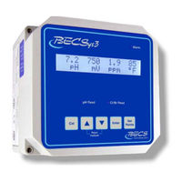
BECS BECSys3 115VAC Operation And Maintenance Manual (23 pages)
Brand:
BECS
| Category:
Controller
| Size: 1 MB
Table of Contents
Table of Contents
3
Warnings
5
General Guidelines
6
Firmware Version
6
Environmental Conditions
6
Electrical Specifications
6
NSF Suggested Operation Ranges
7
Applicable Sensor Operation Ranges
7
Section A: Programming the Controller
8
A - 1: Controller Options
8
A - 2: the Program Menu
8
A - 2.1: Entering the Program Menu
8
A - 2.2: Selecting Language
8
A - 2.3: Ph High Alarm Point
8
A - 2.4: Ph Low Alarm Point
8
A - 2.5: ORP High Alarm Point
8
A - 2.6: ORP Low Alarm Point
9
A - 2.7: Temperature High Alarm Point
9
A - 2.8: Temperature Low Alarm Point
9
A - 2.9: Orp/Ppm Set Point
9
A - 2.10: Ppm High Alarm
9
A - 2.11: Ppm Low Alarm
9
A - 2.12: Exiting the Menu
9
Section B: Normal Operation
10
B - 1: Set Points
10
B - 1.1: Displaying the Set Points
10
B - 1.2: Modifying the Set Points
10
B - 1.2.1: Ph Set Point
10
B - 1.2.2.1: ORP Control
10
B - 1.2.2.2: Ppm Control (Calculated)
10
B - 1.2.2.3: Ppm Control (Probe)
10
B - 1.2.2: Chlorine Set Point
10
B - 1.2.3: Booster Trigger Point
10
B - 2: Single Point Calibration
11
B - 2.1: Single Point Calibration - Ph
11
B - 2.2: Single Point Calibration - Temp
11
B - 2.3: Single Point Calibration - Ppm
11
B - 2.3.1: Calculated Ppm
11
B - 2.3.2: Ppm Probe
11
B - 2.4: Probe Error
11
B - 3: Alarms
11
B - 3.1: Ph High/Low Alarms
11
B - 3.2: ORP High/Low Alarms
11
B - 3.5: no Flow Alarm
12
B - 3.6: Flow Restored Delay
12
B - 3.7: Cl/Br Lockout
12
B - 3.8: Ph Failsafe
12
B - 3.9: Cl/Br Failsafe
12
B - 3.10: Booster FAILSAFE
12
B - 4: Resetting a Failsafe Alarm
12
Section C: Using the Becsysrcm3
13
C - 1: Monitoring a Controller
13
C - 2: Downloading Data Logs
13
C - 2.1: Using a Flash Drive
14
C - 2.1.1: Importing Data Logs
15
C - 3: Viewing Data Logs
15
Section D: Troubleshooting
16
D - 1: Becsys3
16
D - 1.1: Probe Error
16
D - 2: Becsysrcm3
16
D - 2.1: Problems Using a Flash Drive
16
D - 2.2: Text Message Call-Out Test
16
Section E: Maintenance
17
E - 1: Potentiometric Sensors (Ph and ORP)
17
E - 1.1: Electrode Cleaning
17
E - 1.2: Long-Term Storage
17
E - 2: CCS140 Free Chlorine Sensor
17
E - 2.1: Cleaning
17
E - 2.2: Long-Term Storage
17
E - 2.3: Filling Electrolyte
17
Section F: Feed Charts
18
F - 1: Spa Feed Charts
18
F - 2: Pool Feed Charts
19
Section G: Installation Diagrams
20
G - 1: Pressure Filter Installation
20
G - 2: Vacuum Filter Installation
20
Section H: Replacement Parts
21
Section I: Warranty
22
Advertisement
Related Products
BECS BECSys5
BECS BECSys3 230VAC
BECS BECSys7 230VAC
BECS BECSys7 115VAC
BECS BECSys2
BECS Categories
Controller
Lighting Equipment
More BECS Manuals
Login
Sign In
OR
Sign in with Facebook
Sign in with Google
Upload manual
Upload from disk
Upload from URL