Sign In
Upload
Manuals
Brands
Beckhoff Manuals
Adapter
EK9300
Beckhoff EK9300 PROFINET Bus Coupler Manuals
Manuals and User Guides for Beckhoff EK9300 PROFINET Bus Coupler. We have
1
Beckhoff EK9300 PROFINET Bus Coupler manual available for free PDF download: Documentation
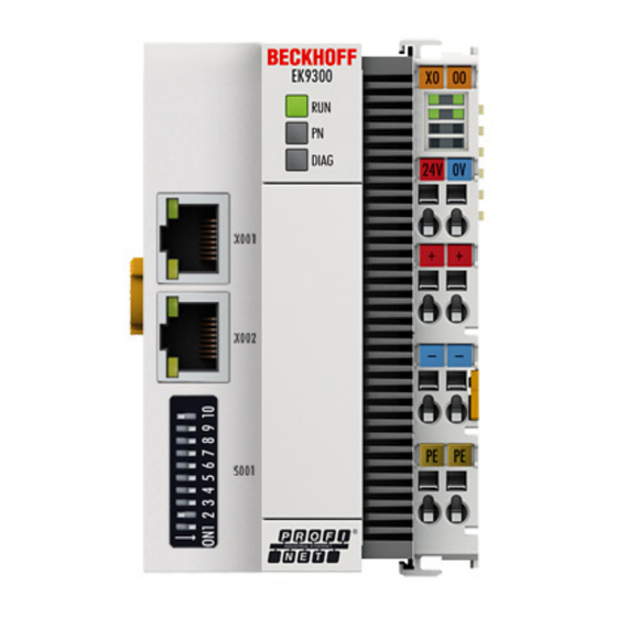
Beckhoff EK9300 Documentation (62 pages)
PROFINET-Bus Coupler for EtherCAT Terminals
Brand:
Beckhoff
| Category:
Adapter
| Size: 4.15 MB
Table of Contents
Table of Contents
3
1 Foreword
5
Notes on the Documentation
5
Safety Instructions
6
Documentation Issue Status
7
Version Identification of Ethercat Devices
7
Fig. 1 EL5021 el Terminal, Standard IP20 IO Device with Serial/ Batch Number and Revision ID (Since 2014/01)
9
Fig. 2 EK1100 Ethercat Coupler, Standard IP20 IO Device with Serial/ Batch Number
9
Fig. 3 CU2016 Switch with Serial/ Batch Number
9
Fig. 4 EL3202-0020 with Serial/ Batch Number 26131006 and Unique ID-Number 204418
10
Fig. 5 EP1258-00001 IP67 Ethercat Box with Batch Number/ Date Code 22090101 and Unique Se- Rial Number 158102
10
Fig. 6 EP1908-0002 IP67 Ethercat Safety Box with Batch Number/ Date Code 071201FF and Unique Serial Number 00346070
10
Fig. 7 EL2904 IP20 Safety Terminal with Batch Number/ Date Code 50110302 and Unique Serial Num- Ber 00331701
10
Fig. 8 ELM3604-0002 Terminal with Unique ID Number (QR Code) 100001051 and Serial/ Batch Num- Ber 44160201
11
Beckhoff Identification Code (BIC)
12
Fig. 9 BIC as Data Matrix Code (DMC, Code Scheme ECC200)
12
2 Product Overview
14
Ekxxxx - System Overview
14
Fig. 10 Ethercat Terminals at an Ekxxxx Series Bus Coupler
14
Technical Data
15
Technical Data PROFINET
16
3 Mounting and Wiring
17
Mounting
17
Instructions for ESD Protection
17
Fig. 11 Spring Contacts of the Beckhoff I/O Components
17
Dimensions
18
Installation on Mounting Rails - Bus Coupler
18
Fig. 12 Ek9Xxx - Dimensions Taking the EK9300 as an Example
18
Fig. 13 EK9300 - Snapping Onto the Mounting Rail
18
Fig. 14 Recommended Distances for Standard Installation Position
19
Wiring
20
Power Supply
20
Fig. 15 Other Installation Positions
20
Fig. 16 Bus Coupler Ek9Xxx Power Supply
21
Ethernet
22
Fig. 17 RJ45 Interface
22
Fig. 18 EK9300 - Topology Sample
25
ATEX - Special Conditions (Standard Temperature Range)
26
ATEX Documentation
26
UL Notice
27
4 Parameterization and Commissioning
28
Meaning of the DIP Switch
28
Further Interfaces
28
Fig. 19: DIP Switch S001: Left off "0", Right on "1
28
Setting the IP Address
29
Fig. 20 Additional Interfaces of the Ek9Xx0
29
5 Configuration
30
Representation of an Ethercat Slave on PROFINET
30
Fig. 21 Typical Configuration Page of an Ethercat Terminal
31
Fig. 22 Example Mapping of an EL3162 in Standard Format ( 8 Byte in / 0 Byte OUT)
32
Fig. 23 Ethercat: Parameter Data of the EL3162 of the ESI under Twincat
33
Fig. 24 PROFINET: Parameter Data of the EL3162 of the GSDML under Twincat
33
EK9300 Configuration
34
EK9300 Ethercat Configuration
36
Fig. 25 Inserting a Sub-Module
36
Fig. 26 Sample Configuration with EK1100 Ethercat Coupler
37
Fig. 27 Sample Configuration with Epxxxx Ethercat Box
38
Fig. 28 Sample Configuration with EK1122 2-Port Ethercat Junction
38
Fig. 29 Sample Configuration with EP1122 2-Port Ethercat Junction
39
EK9300 - Configuration Example
40
Fig. 30 EK9300 - Predefined PDO Selection Dialog
40
Fig. 31 EK9300 Sub-Modules
40
Fig. 32 PROFINET Record Indices 0X3Xxx (Corresponds to Ethercat Objects 0X8Xxx)
41
From Firmware Version 6
42
EK9300 - Coe Data Access over PROFINET
42
Fig. 33 Coe Data Access over PROFINET, Read/Write Sample
42
EK9300 - Multi-Configuration Mode
44
Ek9300 - Io-Link
46
Fig. 34 Inserting a "Generic Channel" (in the Case of IO-Link Devices from Other Manufacturers)
48
From Firmware Version 8
49
Ebus Error Behaviour
49
Fig. 35 Configuration of the IO-Link Device
49
Fig. 36 Adding the GSDML DAP for Firmware FW8.0
49
Fig. 37 the Parameter Ebus Error Behavior
50
Fig. 38 Flag Needebusreset
50
Activating the Web Page
51
Fig. 39 Setting the Parameter Web Server to Active
51
6 Ethernet
52
PROFINET System Presentation
52
Fig. 40 PROFINET System Overview
52
7 Error Handling and Diagnosis
54
Diagnostic Leds
54
Fig. 41 EK9300 Leds
54
8 Appendix
56
Update Bus Coupler Image
56
Ek9300 - Faq
57
List of Abbreviations
57
Support and Service
60
List of Illustrations
61
Advertisement
Advertisement
Related Products
Beckhoff EK9500
Beckhoff EK1110
Beckhoff EK1501-0010
Beckhoff EK1501
Beckhoff EK1122
Beckhoff EK1122-0008
Beckhoff EK1521-0010
Beckhoff EK1561
Beckhoff EK18 Series
Beckhoff EK1814-0000
Beckhoff Categories
Touch terminals
Industrial PC
Control Unit
Touch Panel
Power Supply
More Beckhoff Manuals
Login
Sign In
OR
Sign in with Facebook
Sign in with Google
Upload manual
Upload from disk
Upload from URL