Sign In
Upload
Manuals
Brands
Baxi Manuals
Heat Pump
SYSMGR ALYA 8-10 H WH-A M
Baxi SYSMGR ALYA 8-10 H WH-A M Manuals
Manuals and User Guides for Baxi SYSMGR ALYA 8-10 H WH-A M. We have
2
Baxi SYSMGR ALYA 8-10 H WH-A M manuals available for free PDF download: Installation, User And Service Manual
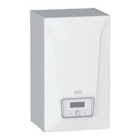
Baxi SYSMGR ALYA 8-10 H WH-A M Installation, User And Service Manual (168 pages)
Reversible air/water "Split Inverter" heat pump
Brand:
Baxi
| Category:
Heat Pump
| Size: 32 MB
Table of Contents
Table of Contents
2
Safety Instructions and Recommendations
6
Safety
6
General Instructions
6
Electrical Wiring
7
Refrigerant
7
About R32 Refrigerant
7
Refrigerant Piping
8
Refrigerant Pipes - Specificities for 12-16 Kw Installations (Directive 2014/68/EU)
8
Water Connections
9
Recommendations
9
Specific Instructions for Service, Maintenance and Breakdowns
10
Liabilities
10
Standard Delivery
11
Symbols Used
11
Symbols Used in the Manual
11
Symbols Used on the Indoor Unit
12
Symbols Used on the Condensate Pan
12
Symbols Used on the Data Plate
12
Technical Specifications
13
Homologations
13
Directives
13
Factory Test
13
Technical Data
13
Compatible Heating Devices
13
Heat Pump
14
Heat Pump Weight
16
Combination Heaters with Medium-Temperature Heat Pump
16
Circulating Pump
20
Sensor Specifications
21
Dimensions and Connections
22
Sysmgr Alya Wh-A
22
Outdoor Unit AWHP2R 4-6 MR
23
Outdoor Unit AWHP2R 8-10-12-16 MR 12-16 TR
24
Heat Pump Schematic Diagram
24
Electrical Diagram
26
Description of the Product
29
Data Plates
29
Main Components
30
Description of the Connection Terminal Blocks
35
Main PCB EHC-09
35
Second Circuit Optional PCB SCB-04
36
Indoor Unit Power Supply
36
Control Panel Description
36
Description of the Interface
36
Description of the Standby Screen
37
Description of Status Icons
37
Description of the Home Screen
37
Description of the Carousel
38
Installation
39
Installation Regulations
39
Respecting the Distance between the Indoor Unit and the Outdoor Unit
39
Positioning the Indoor Unit
40
Choosing the Location of the Indoor Unit
40
Minimum Ground Surface Area and Surface Area of Ventilation Openings
41
Installing Ventilation Openings
42
Installation in a Cupboard
43
Attaching the Indoor Unit to the Wall
43
Accessing the Internal Components
45
Accessing the Indoor Unit Refrigerant System
45
Accessing the Pcbs and Connection Terminal Block
45
Hydraulic Connections
47
Special Precautions for Connecting the Heating Circuit
47
Connecting the Hydraulic Circuits
48
Installing a Domestic Hot Water Tank
50
Connecting the Condensate Drain
51
Flushing the Installation
51
Flushing New Installations and Installations Less than 6 Months Old
51
Flushing an Existing Installation
51
Filling the System
51
Treatment of the Heating Water
51
Filling the Heating Circuit
52
Checking the Heating Circuit
52
Putting the Outdoor Unit in Place
52
Allowing Sufficient Space for the Outdoor Unit
52
Selecting the Location of the Outdoor Unit
53
Choosing the Location of a Noise Abatement Screen
54
Installing the Outdoor Unit on the Ground
54
Selecting the Location of the Outdoor Unit in Cold and Snowy Regions
54
Installing the Outdoor Unit on the Wall Mounting Bracket
55
Removing the Protection from the Outdoor Unit
55
Refrigeration Connections
56
Preparing the Refrigerant Connections
56
Equipment
57
Flaring Work
58
Connecting the Refrigerant Connections to the Indoor Unit
58
Connecting the Refrigerant Connections to the Outdoor Unit
59
Testing the Leak-Tightness of the Refrigeration Connections
60
Pumping down
60
Allow the Refrigerant to Circulate
60
Add Refrigerant if Necessary
61
Labelling the System
61
Protecting the Refrigerant Connections
62
Checking the Refrigeration Circuit
63
Electrical Connections
63
Recommendations
63
Connecting the Electrical Circuits
64
Routing the Cables
65
Connecting the Indoor Unit
66
Connecting the Outdoor Unit to the Power Supply
67
Connecting the Outdoor Unit
68
Fitting the Outdoor Temperature Sensor
68
Connecting a Backup Heater
69
Connecting a Backup Boiler
70
Connecting the Electric Heating Element Power Supply
70
6.10.11 Connecting the Heating Element Power Supply
71
6.10.12 Connecting the Options
73
6.10.13 Connecting an Electricity Meter
73
6.10.14 Checking the Electrical Connections
73
Commissioning
74
General
74
Action to be Taken before Commissioning
74
Commissioning Procedure with Smartphone
74
Commissioning Procedure Without Smartphone
75
Configuration Numbers CN1 et CN2
75
Setting the Flow Rate of the Direct Circuit
76
Final Instructions for Commissioning
77
Settings
77
Accessing the Installer Level
77
Searching for a Parameter or a Measured Value
77
Setting the Circuit Function
78
Configuring the Heating Circuit
78
Setting the Heating Curve
78
Configuring the Cooling Mode
79
Configuring the Backup Boiler
80
Configuring the Backup Boiler Parameters
80
Configuring the Hybrid Operating Mode for a Backup Boiler
80
Drying Screed with or Without an Outdoor Unit
82
Configuring a Room Thermostat
83
Configuring an On/Off or Modulating Thermostat
83
Configuring a Thermostat with a Heating/Cooling Control Contact
84
Configuring the Anti-Legionella Function
85
Configuring a Buffer Tank
86
Improving Comfort
86
Improving Domestic Hot Water or Heating Comfort
86
Configuring Silent Mode
87
Configuring Sources of Energy
88
Configuring an Electricity Meter
88
Supplying the Heat Pump with Photovoltaic Energy
89
Connecting the Installation to a Smart Grid
89
Resetting or Re-Establishing the Parameters
91
Auto-Detecting Options and Accessories
91
Reset the Configuration Numbers CN1 and CN2
91
Reverting to the Factory Settings
91
List of Parameters
91
Installer > Installation Setup > Air Src Heat Pump
92
Installer > Installation Setup > Zone 1 or Zone 2
96
Installer > Installation Setup > Domestic Hot Water (Domestic Hot Water)
99
Installer > Installation Setup > Outdoor Temperature
100
Installer > Installation Setup > SCB-01
102
Installer > Signals
102
Installer > Counters
105
Description of the Parameters
106
Running the Back-Up in Heating Mode
106
Running the Back-Up in Domestic Hot Water Mode
107
Operation of the Switch between Heating and Production of Domestic Hot Water
108
Switching Logic for the Buffer Tank Heating Demand
109
Connection and Installation Examples
110
Installation with Electric Heating Element, Underfloor Heating and Domestic Hot Water Tank
110
Hydraulic Diagram
110
Connecting and Configuring the Heat Pump
111
Installation with Electric Heating Element, Two Circuits and a Buffer Tank Used as a Low-Loss Header
113
Hydraulic Diagram
113
Connecting and Configuring the Heat Pump
114
Installation with Electric Heating Element, Two Circuits and a Low-Loss Header
116
Hydraulic Diagram
116
Connecting and Configuring the Heat Pump
117
Installation with Backup Boiler and One Direct Circuit
119
Hydraulic Diagram
119
Connecting and Configuring the Heat Pump
120
Installation with a Swimming Pool
121
Connecting a Swimming Pool
121
Configuring Swimming Pool Heating
121
10 Operation
122
Regional and Ergonomic Parameters
122
Activate/Deactivate the Child Lock
122
Personalising the Zones
123
Definition of the Term "Zone
123
Changing the Name and Symbol for a Zone
123
Personalising the Activities
124
Definition of the Term "Activity
124
Changing the Name of an Activity
124
Changing the Temperature of an Activity
124
Room Temperature in a Zone
125
Selecting the Operating Mode
125
Setting a Constant Room Temperature
126
Activating and Configuring a Timer Programme for Heating
127
Activating and Configuring a Timer Programme for Cooling
128
Changing the Room Temperature Temporarily
129
Domestic Hot Water Temperature
130
Selecting the Operating Mode
130
Activating and Configuring a Timer Programme for Domestic Hot Water
131
Forcing Domestic Hot Water Production (Override)
132
Modifying the Domestic Hot Water Setpoint Temperatures
133
Managing the Heating, Cooling and Domestic Hot Water Production
134
Shutting off the Heating and Cooling
134
Forcing Cooling
135
Shutting off the Heating in Summer
135
Shutting off Domestic Hot Water Production
136
Periods of Absence or Going on Holiday
136
Frost Protection
138
Monitoring the Energy Consumption
138
Starting and Stopping the Heat Pump
139
Starting the Heat Pump
139
Shutting down the Heat Pump
139
11 Maintenance
140
General
140
Information for Service Personnel
140
List of Inspection and Maintenance Operations
141
Check the Hydraulic Pressure
142
Checking Operation of the Appliance
142
Cleaning the Magnetic Sieve Filters
143
Flushing the Magnetic Screen Filters (Quick Annual Maintenance)
143
Full Cleaning of the Magnetic Sieve Filters
143
Draining the Heating Circuit
144
Replacing the Battery in the Control Panel
144
12 Troubleshooting
145
Resolving Operating Errors
145
Types of Error Code
145
Warning Codes
146
Blocking Codes
146
Lockout Codes
152
Displaying and Clearing the Error Memory
153
Accessing Information on the Hardware and Software Versions
153
Resetting the Safety Thermostat
154
13 Decommissioning and Disposal
154
Decommissioning Procedure
154
Disposal and Recycling
155
Recovery of Refrigerants
155
Labelling
156
Recovery Equipment
156
14 Product Fiche and Package Fiche
156
Product Fiche
156
Product Fiche - Temperature Controller
158
Package Fiche - Combination Heaters (Boilers or Heat Pumps)
159
Package Fiche - Medium-Temperature Heat Pumps
160
15 Appendix
161
Maintenance Information for 12-16 Kw Applications
161
Refrigerant Installation Pre-Commissioning Checklist for 12-16 Kw Applications
162
Name and Symbol of the Zones
163
Name and Temperature of the Activities
164
Advertisement
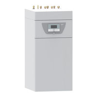
Baxi SYSMGR ALYA 8-10 H WH-A M Installation, User And Service Manual (164 pages)
Reversible air/water "Split Inverter" heat pump
Brand:
Baxi
| Category:
Heat Pump
| Size: 24 MB
Table of Contents
Table of Contents
2
Safety Instructions and Recommendations
6
General Safety Instructions
6
Water Connections
8
Domestic Water Safety
9
Electrical Wiring
9
About R32 Refrigerant
10
Refrigerant Piping
10
Refrigerant Pipes - Specificities for 12-16 Kw Installations (Directive 2014/68/EU)
10
Installation Location
11
Maintenance and Repair Work
11
Explanations Given to the User
12
Recommendations
12
Liabilities
12
Standard Delivery
13
Symbols Used
13
Symbols Used in the Manual
13
Symbols Used on the Data Plate
14
Symbols Used on the Indoor Unit
14
Symbols Used for Connection
14
Technical Specifications
15
Homologations
15
Directives
15
Factory Test
15
Technical Data
15
Compatible Heating Devices
15
Heat Pump
16
Heat Pump Weight
18
Domestic Hot Water Tank
18
Combination Heaters with Medium-Temperature Heat Pump
19
Sensor Specifications
23
Circulating Pump
24
Dimensions and Connections
25
Indoor Unit
25
Outdoor Unit AWHP2R 4-6 MR
26
Outdoor Unit AWHP2R 8-10-12-16 MR 12-16 TR
27
Refrigeration Diagram of the Heat Pump
27
Electrical Diagram
29
Description of the Product
32
Data Plates
32
Main Components
32
Description of the Connection Terminal Blocks
34
Main PCB EHC-09
34
Second Circuit Optional PCB SCB-04
35
Indoor Unit Power Supply
35
Optional PCB for Connection of Impressed Current Anode ACI
35
Description of the User Interface
36
Description of the Interface
36
Description of the Standby Screen
36
Description of Status Icons
36
Description of the Home Screen
37
Description of the Zone Display
37
Description of the Carousel
38
Installation
38
Installation Regulations
38
Respecting the Distance between the Indoor Unit and the Outdoor Unit
39
Positioning the Indoor Unit
39
Choosing the Location of the Indoor Unit
39
Minimum Ground Surface Area and Surface Area of Ventilation Openings
41
Installing Ventilation Openings
41
Installing the Indoor Unit
43
Accessing the Internal Components
43
Hydraulic Connections
44
Connections
44
Special Precautions for Connecting the Heating Circuit
47
Special Precautions for the Connection of the Domestic Hot Water Circuit
48
Connecting the Safety Valve Drain Pipe
49
Flushing the Installation
49
Flushing New Installations and Installations Less than 6 Months Old
49
Flushing an Existing Installation
49
Filling the System
49
Filling the Heating Circuit
49
Checking the Heating Circuit
50
Filling the Domestic Hot Water Circuit
51
Putting the Outdoor Unit in Place
51
Allowing Sufficient Space for the Outdoor Unit
51
Selecting the Location of the Outdoor Unit
52
Choosing the Location of a Noise Abatement Screen
52
Installing the Outdoor Unit on the Ground
52
Selecting the Location of the Outdoor Unit in Cold and Snowy Regions
53
Installing the Outdoor Unit on the Wall Mounting Bracket
54
Removing the Protection from the Outdoor Unit
54
Refrigeration Connections
55
Preparing the Refrigerant Connections
55
Equipment
56
Flaring Work
56
Connecting the Refrigerant Connections to the Indoor Unit
57
Connecting the Refrigerant Connections to the Outdoor Unit
58
Testing the Leak-Tightness of the Refrigeration Connections
59
Pumping down
59
Allow the Refrigerant to Circulate
59
Add Refrigerant if Necessary
60
Labelling the System
61
Protecting the Refrigerant Connections
61
Checking the Refrigeration Circuit
62
Electrical Connections
62
Recommendations
62
Connecting the Electrical Circuits
64
Routing the Cables
65
Connecting the Indoor Unit to the Power Supply
65
Connecting the Outdoor Unit to the Power Supply
66
Connecting the Outdoor Unit to the Indoor Unit
67
Connecting the Outdoor Temperature Sensor
67
Connecting a Backup Boiler
69
Connecting and Configuring the Immersion Heater (Electrical Backup)
69
6.10.10 Connecting an Electricity Meter
71
6.10.11 Checking the Electrical Connections
71
Commissioning
71
General
71
Action to be Taken before Commissioning
72
Commissioning Procedure with Smartphone
72
Commissioning Procedure Without Smartphone
72
CN1 and CN2 Parameters
73
Setting the Flow Rate of the Direct Circuit
73
Setting the Flow Rate of the Internal Second Circuit
74
Final Instructions for Commissioning
75
Settings
75
Accessing the Installer Level
75
Activating/Deactivating the Bluetooth ® for the Appliance
76
Searching for a Parameter or a Measured Value
76
Setting the Circuit Function
76
Configuring the Heating Circuit
77
Setting the Heating Curve
77
Configuring the Cooling Mode
78
Configuring the Backup Boiler
79
Configuring the Backup Boiler Parameters
79
Configuring the Hybrid Operating Mode for a Backup Boiler
79
Drying Screed with or Without an Outdoor Unit
80
Configuring a Room Thermostat
82
Configuring an On/Off or Modulating Thermostat
82
Configuring a Thermostat with a Heating/Cooling Control Contact
82
Configuring the Anti-Legionella Function
83
Configuring a Buffer Tank
84
Improving Comfort
85
Improving Domestic Hot Water or Heating Comfort
85
Configuring Silent Mode
85
Configuring Sources of Energy
86
Configuring an Electricity Meter
86
Supplying the Heat Pump with Photovoltaic Energy
87
Connecting the Installation to a Smart Grid
87
Resetting or Re-Establishing the Parameters
89
Resetting the Configuration Numbers
89
Auto-Detecting Options and Accessories
89
Reverting to the Factory Settings
89
Parameters
89
List of Parameters
89
Installer > Installation Setup > Air Src Heat Pump
90
Installer > Installation Setup > Zone1 or Zone2
94
Installer > Installation Setup > Domestic Hot Water (Domestic Hot Water)
97
Installer > Installation Setup > Outdoor Temperature
98
Bluetooth
99
Installer > Signals
100
Description of the Parameters
103
Running the Back-Up in Heating Mode
103
Running the Back-Up in Domestic Hot Water Mode
104
Operation of the Switch between Heating and Production of Domestic Hot Water
105
Operation of the Heating Curve
106
10 Connection and Installation Examples
108
Installation with One Immersion Heater and One Direct Circuit
108
Hydraulic Diagram
108
Connecting and Configuring the Heat Pump
109
Installation with One Immersion Heater and Two Circuits
110
Hydraulic Diagram
110
Connecting and Configuring the Heat Pump
111
Installation with 2 Circuits and a Buffer Tank Used as a Low-Loss Header
113
Hydraulic Diagram
113
Connecting and Configuring the Heat Pump
114
Installation with a Swimming Pool
116
Connecting a Swimming Pool
116
Configuring Swimming Pool Heating
116
11 Operation
117
Regional and Ergonomic Parameters
117
Activate/Deactivate the Child Lock
117
Personalising the Zones
118
Definition of the Term "Zone
118
Changing the Name and Symbol for a Zone
118
Personalising the Activities
119
Definition of the Term "Activity
119
Changing the Name of an Activity
119
Changing the Temperature of an Activity
119
Room Temperature in a Zone
120
Selecting the Operating Mode
120
Setting a Constant Room Temperature
121
Activating and Configuring a Timer Programme for Heating
122
Activating and Configuring a Timer Programme for Cooling
123
Changing the Room Temperature Temporarily
124
Domestic Hot Water Temperature
125
Selecting the Operating Mode
125
Activating and Configuring a Timer Programme for Domestic Hot Water
126
Forcing Domestic Hot Water Production (Override)
128
Modifying the Domestic Hot Water Setpoint Temperatures
128
Managing the Heating, Cooling and Domestic Hot Water Production
129
Shutting off the Heating and Cooling
129
Forcing Cooling
130
Shutting off the Heating in Summer
130
Shutting off Domestic Hot Water Production
131
Periods of Absence or Going on Holiday
131
Frost Protection
133
Monitoring the Energy Consumption
133
Starting and Stopping the Heat Pump
134
Starting the Heat Pump
134
Shutting down the Heat Pump
135
12 Maintenance
135
General
135
Information for Service Personnel
136
List of Inspection and Maintenance Operations
136
Draining the Heating Circuit
137
Draining the Domestic Hot Water Circuit
138
Cleaning the Magnetic Sieve Filters
138
Position of the Magnetic Sieve Filters
138
Flushing the Magnetic Screen Filters (Quick Annual Maintenance)
138
Full Cleaning of the Magnetic Sieve Filters
139
Checking the Magnesium Anode
139
Impressed Current Anode ACI
140
Check the Hydraulic Pressure
141
12.10 Checking Operation of the Appliance
141
12.11 Replacing the User Interface Battery
141
13 Troubleshooting
142
Resolving Operating Errors
142
Types of Error Code
142
Warning Codes
142
Blocking Codes
143
Lockout Codes
149
Displaying and Clearing the Error Memory
150
Accessing Information on the Hardware and Software Versions
150
Resetting the Safety Thermostat
151
14 Decommissioning and Disposal
151
Decommissioning Procedure
151
Disposal and Recycling
151
Recovery of Refrigerants
152
Labelling
152
Recovery Equipment
152
15 Product Fiche and Package Fiche
153
Product Fiche
153
Product Fiche - Temperature Controller
155
Package Fiche - Medium-Temperature Heat Pumps
155
Package Fiche - Combination Heaters (Boilers or Heat Pumps)
158
16 Appendix
159
Maintenance Information for 12-16 Kw Applications
159
Refrigerant Installation Pre-Commissioning Checklist for 12-16 Kw Applications
160
Name and Symbol of the Zones
161
Name and Temperature of the Activities
161
Advertisement
Related Products
Baxi ALYA WH-A Series
Baxi SYSMGR ALYA 4-6 E WH-A M
Baxi SYSMGR ALYA 4-6 E-EXP
Baxi SYSMGR ALYA 8-10 E WH-A M
Baxi SYSMGR ALYA 8-10 E-EXP
Baxi SYSMGR ALYA 12-16 E WH-A M
Baxi SYSMGR ALYA 4-6 H WH-A M
Baxi SYSMGR ALYA 12-16 H WH-A M
Baxi ALYA FS-A Series
Baxi Ambiflo 75
Baxi Categories
Boiler
Indoor Fireplace
Heat Pump
Water Heater
Air Conditioner
More Baxi Manuals
Login
Sign In
OR
Sign in with Facebook
Sign in with Google
Upload manual
Upload from disk
Upload from URL