Sign In
Upload
Manuals
Brands
Baumer Manuals
Media Converter
Hubner Berlin PMG10
Baumer Hubner Berlin PMG10 Manuals
Manuals and User Guides for Baumer Hubner Berlin PMG10. We have
3
Baumer Hubner Berlin PMG10 manuals available for free PDF download: Operating Manual, Mounting And Operating Instructions
Baumer Hubner Berlin PMG10 Operating Manual (44 pages)
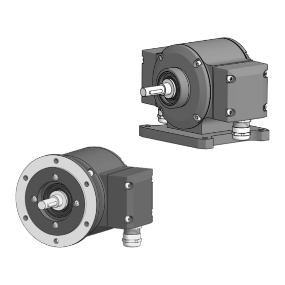
Absolute Encoder
Brand:
Baumer
| Category:
Media Converter
| Size: 2.9 MB
Table of Contents
List of Contents
2
Table of Contents
2
Labels in this Manual
4
Disclaimer
4
About this Document
4
Warnings in this Manual
4
Purpose
4
Scope of Delivery
5
Name Plate
5
Maintenance and Service Life
5
Approvals and Warranty
5
Mounting Accessories
5
Temperature Range for Operation and Storage
6
General Information
7
Transport and Storage
8
Transport
8
Delivery Inspection
8
Storage
8
Description
9
Rotary Encoder
9
Ill. 1 Description PMG10
9
Ill
10
Required Tools
10
Mounting Accessories (Not Included)
10
Installation
11
Mounting with EURO Flange B10
11
Attach Coupling Onto Encoder Shaft
11
Ill. 3 Attach Coupling Onto Encoder Shaft
11
Mounting Encoder Onto Drive Shaft
12
Ill. 4 Installing Encoder, Mounting Device and Coupling
13
Ill. 5 Attach Coupling Onto Encoder Shaft
14
Attach Coupling Onto Encoder Shaft
14
Mounting with Base B3
14
Mounting Encoder Onto Drive Shaft
15
Ill. 6 Mounting Encoder Onto Drive Shaft
16
Maximum Permitted Tolerances for Mounting Errors When Using the Baumer Hübner K 35 Spring
17
Ill. 7 Permissible Mounting Errors (Dimensions in MM)
17
Notes When Using a Claw Coupling (E.g. ROTEX®)
18
Ill. 8 Correct Assembly of a Claw Coupling
18
Electrical Installation
19
Connections
20
RESET" Function
21
Function Direction of Rotation
21
Data Transfer
21
SSI Interface
21
Output Signals Additional Incremental Output (Optional)
22
Switching Level Additional Output Incremental (Optional)
22
Programming Interface (Only for Programmable Variant)
22
Ill. 9 Output Signals with Positive Direction of Rotation (Zero Pulse R+ and R- Are Only Available at Addi- Tional Output II)
22
LED Activity Indicator
23
Output Switching Behavior Speed Switch (Optional)
23
Electrical Connection with Radial Terminal Boxes
24
Connecting the Supply Cable
24
Ill. 10 Connecting the Supply Cable
24
Pin Assignment First Terminal Box
26
Ill. 11 Pin Assignment
26
Assignment of Connection Elements Second Terminal Box
27
Electrical Connection with Radial Flange Connector
27
Connecting the Supply Cable
27
Ill. 12 Pin Assignment
27
Assignment First Flange Connector
29
Ill. 13 Flange Socket M23 (Male, 17-Pin, Clockwise)
29
Assignment Second Flange Connector
30
Ill. 14 Flange Socket M23 (Male, 12-Pin, Clockwise)
30
Ill. 15 Z-PA.SDL.1 WLAN Adapter (Ordering Ref.: 11190106)
31
Sensor Cable and Round Connector
31
Z-PA.SDL.1 WLAN Adapter: Programming Device for HMG10P/PMG10P
31
Sensor Cable
31
Round Connector M23
32
Round Connector M23, 17-Pin with Sensor Cable HEK17
32
For Devices W/O Additional Incremental Output
32
For Encoders with Additional Incremental Output
34
Disassembly
35
Uninstall When Using EURO Flange B10
36
Uninstall Encoder from Drive Shaft
36
Ill. 16 Uninstall Encoder, Mounting Device and Coupling
36
Ill. 17 Uninstall Encoder, Mounting Device and Coupling
38
Uninstall with Base B3
38
Uninstall Encoder from Drive Shaft
38
Technical Data
40
Solid Shaft Encoder Dimensions with EURO Flange B10
41
With Radial Terminal Boxes
41
Ill. 18 Dimensions of Solid Shaft Encoder with EURO Flange B10 and Radial Terminal Boxes (All in MM, Un- Less Specified Otherwise)
41
With Radial Flange Connectors
42
Solid Shaft Encoder Dimensions with Housing Base B3
42
Ill. 19 Dimensions of the Solid Shaft Encoder with EURO Flange B10 with Radial Flange Sockets (All in MM, Unless Specified Otherwise)
42
Ill. 20 Solid Shaft Encoder Dimensions with Housing Base B3 (All in MM Unless Specified Otherwise)
42
List of Illustrations
43
Advertisement
Baumer Hubner Berlin PMG10 Mounting And Operating Instructions (32 pages)
Absolute encoder DeviceNet with magnetic sensing
Brand:
Baumer
| Category:
Media Converter
| Size: 2.84 MB
Table of Contents
Table of Contents
2
1 Importent Notes
4
1�1 Symbol Guide
4
1�2 Intended Use
4
1�3 Exclusion from Liability
4
1�4 Maintenance and Service Life
5
1�5 Approvals and Warranty
5
1�6 Operating and Storage Temperature Range
5
1�7 Disposal (Environmental Protection)
5
Safety and Attention Instructions
6
2�1 Safety Instructions
6
2�2 Attention Instructions for Mounting and Operation
7
2 Preparation
8
3�1 Scope of Delivery
8
3�2 Required Accessory for Mounting (Not Included in Scope of Delivery)
9
3�3 Required Tools (Not Included in Scope of Delivery)
9
Mounting
10
3 Euro Flange B
10
4�1�1 Mounting the Spring Disk Coupling to the Device
10
4�1�2 Mounting to the Drive Shaft
10
4�1�3 Mounting the Spring Disk Coupling to the Drive Shaft
11
4�2 Housing Foot B3
12
4�2�1 Mounting the Spring Disk Coupling to the Device
12
4 �2�2 Mounting to the Drive Shaft
12
4�2�3 Mounting the Housing Foot and the Spring Disk Coupling to the Drive Shaft
13
4�4 Note When Using a Jaw-Type Coupling (for Example „ROTEX®")
15
Electrical Connection
16
5�1 Devicenet
16
5 �1�1 Features
16
5�1�2 Bus Connecting Box Devicenet [ a ] with Cable Glands - Cable Connection
17
5�1�3 Bus Connecting Box Devicenet [ a ] with Connectors - Assignment Connectors
18
5�1�3�1 View a 1 - Connector M12 (Male, 5-Pin, A-Coded)
18
5�1�3�2 View a 2 - Connector M12 (Female, 5-Pin, A-Coded)
18
5�1�4 View in Bus Connecting Box Devicenet
19
5�1�5 Setting for the Terminating Resistors
19
5�1�6 Setting for the User Address
19
5�1�7 Setting for the Transmission Rate
20
5�2 Terminal Box
20
Terminal Significance
20
5�2�2 Additional Output Incremental (Option)
21
5�2�2�1 Output Signals
21
5�2�2�2 Trigger Level
21
5�2�3 LED Function Displays
21
5�2�4 Programming Interface (Only PMG10P)
22
5�2�5 Switching Characteristics Speed Switch (Option)
22
5�2�6 Cable Connection
23
5�2�7 Assignment Connecting Terminal
24
5�3 Accessory Z-PA�SDL�1 WLAN Adapter: Programming Device for PMG10P
24
Dimensions
25
Euro Flange B10
25
6�2 Housing Foot B3
26
Dismounting
27
Euro Flange B10
27
7�2 Housing Foot B3
28
6 Technical Data
29
8�1 Technical Data - Electrical Ratings
29
8�2 Technical Data - Electrical Ratings (Speed Switches)
29
8 �3 Technical Data - Mechanical Design
30
Baumer Hubner Berlin PMG10 Mounting And Operating Instructions (32 pages)
Incremental encoder with magnetic sensing
Brand:
Baumer
| Category:
Media Converter
| Size: 2.99 MB
Table of Contents
Table of Contents
2
1 Importent Notes
4
1�1 Symbol Guide
4
1�2 Intended Use
4
1�3 Exclusion from Liability
4
1�4 Maintenance and Service Life
5
1�5 Approvals and Warranty
5
1�6 Operating and Storage Temperature Range
5
1�7 Disposal (Environmental Protection)
5
Safety and Attention Instructions
6
2�1 Safety Instructions
6
2�2 Attention Instructions for Mounting and Operation
7
2 Preparation
8
3�1 Scope of Delivery
8
3�2 Required Accessory for Mounting (Not Included in Scope of Delivery)
9
3�3 Required Tools (Not Included in Scope of Delivery)
9
Mounting
10
3 Euro Flange B
10
4�1�1 Mounting the Spring Disk Coupling to the Device
10
4�1�2 Mounting to the Drive Shaft
10
4 Mounting
12
4�2 Mounting with Housing Foot B3
12
4�2�1 Mounting the Spring Disk Coupling to the Device
12
4�2�2 Mounting to the Drive Shaft
12
4�2�3 Mounting the Housing Foot and the Spring Disk Coupling to the Drive Shaft
13
Coupling Is Used
14
4�4 Note When Using a Jaw-Type Coupling (for Example „ROTEX®")
15
5 Electrical Connection
16
Terminal Significance
16
5�2 Output Signals
16
5�3 Trigger Level
17
5�4 Programming Interface (Only PMG10P)
17
5�5 LED Function Displays
17
5�6 Speed Switch (Option) - Switching Characteristics
18
5�7 Cable Connection
19
5�8 Assignment Connecting Terminal
20
Assignment Flange Connector M23
22
Accessories
25
6�1 Z-PA�SDL�1 WLAN Adapter: Programming Device for PMG10P
25
6 �2 Sensor Cable
25
Dimensions
26
Euro Flange B12
26
Euro Flange B10 And Flange Connector M23
27
7 �3 Housing Foot B3 and Terminal Box
28
Dismounting
29
Euro Flange B10
29
8�2 Housing Foot B3
30
8 Technical Data
31
9�1 Technical Data - Electrical Ratings
31
9�2 Technical Data - Electrical Ratings (Speed Switch)
31
9�3 Technical Data - Mechanical Design
32
Advertisement
Advertisement
Related Products
Baumer HUBNER BERLIN FSL
Baumer HUBNER BERLIN HMG10
Baumer HUBNER BERLIN PROFI NET microGen HMG10
Baumer HUBNER BERLIN DeviceNet HMG 10
Baumer Hubner Berlin PMG 10
Baumer HUBNER BERLIN SAFETY POG 90 + ESL 93
Baumer Hubner Berlin HOG 16 M + DSL
Baumer Hubner Berlin CANopen PMG 10
Baumer Hubner Berlin microGen PMG10
Baumer Hubner Berlin microGen PMG10 EtherNet/IP
Baumer Categories
Accessories
Media Converter
Security Sensors
Measuring Instruments
Portable Generator
More Baumer Manuals
Login
Sign In
OR
Sign in with Facebook
Sign in with Google
Upload manual
Upload from disk
Upload from URL