Sign In
Upload
Manuals
Brands
Basler Vision Technologies Manuals
Digital Camera
Sprint Series
Basler Vision Technologies Sprint Series Manuals
Manuals and User Guides for Basler Vision Technologies Sprint Series. We have
1
Basler Vision Technologies Sprint Series manual available for free PDF download: User Manual
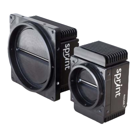
Basler Vision Technologies Sprint Series User Manual (236 pages)
MONO CAMERAS
Brand:
Basler Vision Technologies
| Category:
Digital Camera
| Size: 2 MB
Table of Contents
Table of Contents
5
1 Specifications, Requirements, and Precautions
11
Document Applicability
11
General Specifications
12
Camera Models with 2K Pixels
12
Camera Models with 4K Pixels
13
Camera Models with 8K Pixels
14
Lens Adapters
15
Lens Adapters for 2K and 4K Cameras
15
Lens Adapters for 8K Cameras
15
Adapting with the UNIFOC 100/95_/_V-Basler Helical Mount
16
Adapting with the M58 X 0.75_/_V-Basler Lens Mount
18
Spectral Response
20
Mechanical Specifications
21
Camera Dimensions and Mounting Points for 2K and 4K Cameras
21
Sensor Positioning Accuracy for 2K and 4K Cameras
23
Sensor Line Location for 2K and 4K Cameras
24
F-Mount Adapter Dimensions (2K and 4K Cameras)
25
Camera Dimensions and Mounting Points for 8K Cameras
25
Sensor Positioning Accuracy for 8K Cameras
27
Sensor Line Location for 8K Cameras
28
Environmental Requirements
29
Temperature and Humidity
29
Heat Dissipation
29
Precautions
30
2 Physical Interface
33
General Description of the Connections
34
Connector Pin Assignments and Numbering
35
Pin Assignments for the MDR Connectors
35
Pin Assignments for the 6-Pin Micro-Miniature Receptacle
37
Pin Numbering
37
Connector Types
38
26-Pin Connectors
38
6-Pin Connector
38
Cabling Requirements
39
Camera Link Cable
39
Power Cable
39
Camera Power
40
Camera Link Implementation
41
Input Signals
43
Serial to Camera
43
External Sync (Exsync)
43
Output Signals
44
Line Valid Bit
44
Data Valid Bit
44
Pixel Data Bits
44
Camera Link Pixel Clock
45
Serial to Frame Grabber
46
Serial Communication
47
Making the Serial Connection
47
3 Line Acquisition Modes
49
Introduction
49
Single Line [Max 70 Khz] Acquisition Mode
50
Dual Line [Max 140 Khz] Acquisition Modes
51
Vertical Binning Acquisition Mode
59
Time Delayed Line Summing Acquisition Mode
61
Line Averaging Acquisition Mode
67
Time Delayed Line Averaging Acquisition Mode
68
Horizontal Binning
69
Averaging
71
Camera Operating Recommendations
71
System Design Recommendations
71
System Design Calculations
73
4 Exposure Start and Exposure Time Control
77
Exsync Controlled Operation
77
Basics of Exsync Controlled Operation
77
Selecting an Exsync Exposure Mode & Setting the Exposure Time
79
Guidelines When Using an Exsync Signal
79
Free Run
81
Basics of Free Run Controlled Operation
81
Selecting a Free Run Exposure Mode, Setting the Line Period, and Setting the Exposure Time
82
Guidelines When Using Free Run
83
Maximum Allowed Line Rate / Minimum Line Period
84
Max Segment AOI Pixels
87
Example of Calculating the Maximum Allowed Line Rate / Minimum
90
Line Period
90
Increasing the Maximum Allowed Line Rate
91
Camera Settings for the Maximum Specified Line Rate
92
5 Video Data Output Modes
95
Overview
95
Setting the Video Data Output Mode
97
Video Data Output Mode Details
98
Tap Output Modes
98
Video Data Sequence for 2 Tap Output Modes
99
Line Valid Delays for 2 Tap Output Modes
103
Tap Output Modes
106
Video Data Sequence for 4 Tap Modes
107
Line Valid Delays for 4 Tap Output Modes
112
Tap 8 Bit Output Mode
115
Video Data Sequence for 8 Tap 8 Bit Mode
115
Line Valid Delays for 8 Tap Output Modes
122
6 Features
125
Gain and Offset
125
Gain
125
Offset
126
Area of Interest
128
Setting the AOI
130
Shading Correction
131
Enabling Shading Correction
132
Generating and Saving User Shading Correction Values
133
Activating a Shading Values File
138
Copying the Factory Shading Values into the User Shading Values File
139
Downloading a Shading Values File to Your PC
140
Uploading a Shading Values File to Your Camera
141
Test Images
142
Test Image One (Fixed Gradient)
143
Test Image Two (Moving Gradient)
144
Test Image Three (Uniform Black)
145
Test Image Four (Uniform Gray)
145
Line Stamp
146
Enabling and Setting the Line Stamp
150
Lookup Table
151
Imaging Sensor Temperature
154
Camera Power Undervoltage and Overvoltage Protection
155
Error Condition Detection
156
Imaging Sensor Overtemperature Condition Detected
156
Camera Power Overvoltage Condition Detected
157
Camera Status Checks
158
Camera Reset
158
Configuration Sets
159
Saving the Work Set to a User Set File
161
Activating" a User Set File or the Factory Set File
162
Which Configuration Set File will Load at Startup or at Reset
163
Downloading Configuration Set Files to Your PC
163
Uploading Configuration Set Files to Your Camera
164
7 Configuring the Camera
165
Configuring the Camera with the Camera Configuration Tool Plus (CCT+)
166
Configuring the Camera by Setting Registers
167
Inquiry Registers
168
Inquiry Register Details
168
Model Information Inquiry
168
Vendor Information Inquiry
168
Camera Version Inquiry
169
Product ID Inquiry
169
Serial Number Inquiry
169
Firmware Version Inquiry
170
Camera Status Inquiry
171
FPGA Status Inquiry
172
Binary Command Protocol Status Inquiry
173
Imaging Sensor Temperature Inquiry
173
Feature Control and Status Registers
174
Raw" Value Fields Vs. "Absolute" Value Fields
174
Camera Link Clock Speed CSR
176
Feature Control and Status Register Details
176
Video Data Output Mode CSR
176
Line Acquisition Mode CSR
177
Exposure Time Control Mode CSR
178
Horizontal Binning CSR
178
Exposure Time CSR
179
Line Period CSR
181
Gain CSR
183
Offset CSR
184
Area of Interest Starting Pixel CSR
186
Area of Interest Length CSR
187
Shading Mode CSR
188
Shading Value Generate CSR
188
Test Image Mode CSR
189
Line Stamp Mode CSR
190
Line Stamp Low Pixel Limit CSR
191
Line Stamp High Pixel Threshold CSR
192
Lookup Table Mode CSR
193
Lookup Table Index CSR
194
Lookup Table Value CSR
195
Camera Reset CSR
196
Serial Communication CSR
197
Bulk Data and the Bulk Data Control and Status Registers
198
Using the Configuration Set Bulk Data CSR
199
Using the Shading Values Bulk Data CSR
200
General Procedures for Working with Bulk Data Csrs
201
Bulk Data Control and Status Register Details
204
Configuration Set CSR
204
Shading Values CSR
205
Using Binary Read/Write Commands
206
The Binary Read/Write Command Protocol
207
Error Checking and Responses
210
Basic Read/Write Command Explanations
211
Read Command
211
Write Command
212
Calculating the Block Check Character
213
Binary Command Sample Code
214
8 Troubleshooting and Support
215
Tech Support Resources
215
Fault Finding Using the Camera LED
216
Troubleshooting Charts
218
No Image
219
Poor Quality Image
221
Interfacing
222
Serial Communication
223
RS-644 Serial Communication
223
Before Calling Basler Technical Support
224
Revision History
227
Feedback
231
Index
233
Advertisement
Advertisement
Related Products
Basler Vision Technologies Basler scout scA640-70gm
Basler Vision Technologies Basler scout scA640-74gm
Basler Vision Technologies Basler scout scA750-60gm
Basler Vision Technologies Basler scout scA640-70gc
Basler Vision Technologies Basler scout scA640-74gc
Basler Vision Technologies Basler scout scA750-60gc
Basler Vision Technologies Sprint
Basler Vision Technologies A202k
Basler Vision Technologies A202kc
Basler Vision Technologies Categories
Digital Camera
IP Camera
CCD Cameras
More Basler Vision Technologies Manuals
Login
Sign In
OR
Sign in with Facebook
Sign in with Google
Upload manual
Upload from disk
Upload from URL