Sign In
Upload
Manuals
Brands
Bard Manuals
Heat Pump
Q60H3-A
User Manuals: Bard Q60H3-A Air-to-Air Heat Pump
Manuals and User Guides for Bard Q60H3-A Air-to-Air Heat Pump. We have
1
Bard Q60H3-A Air-to-Air Heat Pump manual available for free PDF download: Installation Instructions Manual
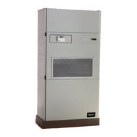
Bard Q60H3-A Installation Instructions Manual (42 pages)
Q-TEC SERIES PACKAGED HEAT PUMP
Brand:
Bard
| Category:
Heat Pump
| Size: 1.17 MB
Table of Contents
Installation Instructions
1
Table of Contents
2
Getting Other Information and Publications
3
Q-TEC Series General Information
4
Q-TEC Model Nomenclature
4
Factory Built-In Electric Heat
4
Table 3 Table
4
Table 5 Table
5
Electrical Specifications
5
Figure 1 Unit Dimensions
6
Figures
6
Figure 2 Air Seal on Bottom of Unit
7
Figure 3 Removal of Unit from Skid
7
Shipping Damage
7
Unit Removal from Skid
7
Figure 4 Unit on Appliance Cart for Moving
8
General
8
Handling Unit after Removal from Skid
8
Minimum Installation Height
8
Figure 5 Installation with Duct-Free Plenum
9
Figure 6 Ducted Application
9
Duct Work
10
Figure 7 Supply Duct Connections
10
Figure 8 Filter Location
10
Filters
10
Condensate Drain
11
Fresh Air Intake
11
Optional Rear Drain Kits
11
Service Light
11
Figure 10 Standard Rear Drain
12
Figure 11 Rear Drain (Top View)
12
Figure 9 Optional Side Drain
12
Figure 12A Optional Rear Drain Kit
13
Figure 12B Optional Rear Drain Kit
14
Figure 12C Optional Rear Drain Kit
15
Figure 12D Optional Rear Drain Kit
16
Figure 13A Unit Mounting - Method 1
17
Figure 13B Unit Mounting - Method 2
17
Installation
18
Mounting the Unit
18
Wiring - Main Power
19
Wiring - Low Voltage
19
Optional Climate Controls Sequence of Operation
19
Figure 15 Component Location
19
Operating Voltage Range
19
Low Voltage Connections
20
General
20
Figure 23 CO
20
Figure 16 Thermostat Plug Terminals
21
Table 4
21
Wall Thermostats
21
Figure 17A T-Stat Wiring Diagram "X" Opt
22
Figure 17B T-Stat Wiring Diagram "X" Opt. W/Demand .23 Figure 18 T-Stat Wiring Diagram "D" Opt
24
Figure 19 T-Stat Wiring Diagram "H" Option
25
Figure 20 T-Stat Wiring Diagram "B" or "C" Opt
26
Tables
21
Tart up
27
R-410A Refrigerant: General
27
Topping off System Charge
27
Safety Practices
27
Description of Standard Equipment
28
Optional CFM (Q36, Q42, Q48 and Q60 Only)
28
Important Installer Note
28
Phase Monitor
28
Three Phase Scroll Compressor Start up Info
28
Service Hints
29
Mist Eliminator Service
29
Vent Options
30
Figure 21 Fresh Air Damper Removal
31
Figure 22 QERV Removal
32
Controller
33
Sequence of Operation
33
Pressure Service Ports
34
Defrost Cycle
34
Figure 24 Defrost Control Board
35
Troubleshooting
36
Solid State HP Control Troubleshooting Procedure
36
Table 7 Table
37
Checking Temperature Sensor
37
Temp. Vs Resistance of Temp. Sensor
37
Troubleshooting ECM™ Blower Motors
38
Moisture Check
38
Figure 25 Control Disassembly
39
Figure 26 Winding Test
39
Figure 27 Drip Loop
39
Figure 28 Fan Blade Setting
40
Fan Blade Setting Dimensions
40
Refrigerant Charge
40
Fan Blade Dimension
40
Indoor Blower Performance
40
Cooling Pressure
41
Manual 2100-652A
41
Table 10 Heating Pressure
42
Advertisement
Advertisement
Related Products
Bard Q60H3-C
Bard Q-TEC Q60H3DA
Bard Q-TEC Q60H3DB
Bard Q-TEC Q60H3DA0Z
Bard Q-TEC Q60H3DA10
Bard Q-TEC Q60H3DA15
Bard Q-TEC Q60H3DB09
Bard Q-TEC Q60H3DB15
Bard Q-TEC Q60H3DC0Z
Bard Q-TEC Q60H3DC15
Bard Categories
Air Conditioner
Heat Pump
Medical Equipment
Furnace
Controller
More Bard Manuals
Login
Sign In
OR
Sign in with Facebook
Sign in with Google
Upload manual
Upload from disk
Upload from URL