Sign In
Upload
Manuals
Brands
Banner Manuals
Controller
6075133159
Banner 6075133159 Manuals
Manuals and User Guides for Banner 6075133159. We have
1
Banner 6075133159 manual available for free PDF download: Instruction Manual
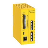
Banner 6075133159 Instruction Manual (195 pages)
Safety Controller
Brand:
Banner
| Category:
Controller
| Size: 7.93 MB
Table of Contents
Table of Contents
2
About this Document
5
Important
5
Use of Warnings and Cautions
5
EU Declaration of Conformity (Doc)
5
Product Description
7
Terms Used in this Manual
7
Software
7
USB Connections
7
Ethernet Connections
7
Internal Logic
8
Password Overview
8
SCR P-PA Programming Tool
8
SCR P Overview
9
SCR P Models
9
SCR P Features and Indicators
9
SCR P Using FID 2 Safety Controllers
10
Input and Output Connections
10
SCR P Safety and Non-Safety Input Devices
10
SCR P Safety Relay Outputs
10
SCR P Status Outputs and Virtual Status Outputs
11
SCR P Automatic Terminal Optimization (ATO) Feature with External Terminal Blocks (ETB)
11
Specifications and Requirements
12
SCR P Specifications
12
Dimensions
15
PC Requirements
15
System Installation
16
Installing the Software
16
Installing the Safety Controller
16
Mounting Instructions
16
Installation Considerations
17
Appropriate Application
17
SCR P Applications
17
Safety Input Devices
18
Safety Circuit Integrity and ISO 13849-1 Safety Circuit Principles
19
Safety Input Device Properties
20
Safety Input Device Options
22
Safety Circuit Integrity Levels
23
Emergency Stop Push Buttons
23
Rope (Cable) Pull
24
Enabling Device
24
Protective (Safety) Stop
24
Interlocked Guard or Gate
25
Optical Sensor
25
Two-Hand Control
26
Safety Mat
28
Muting Sensor
31
Bypass Switch
32
Adjustable Valve Monitoring (AVM) Function
33
DCD Inputs
34
Non-Safety Input Devices
35
Manual Reset Input
36
Virtual Non-Safety Input Devices
37
Virtual Manual Reset and Cancel Delay (RCD) Sequence
38
Virtual ON/OFF and Mute Enable
41
Safety Outputs
41
Safety Relay Outputs
44
EDM and FSD Hookup
44
Status Outputs
50
Status Output Signal Conventions
50
Status Output Functionality
50
Virtual Status Outputs
51
Getting Started
52
Creating a Configuration
52
Adding Inputs and Status Outputs
52
Adding Safety and Non-Safety Inputs
52
Adding Status Outputs
55
Designing the Control Logic
56
Saving and Confirming a Configuration
56
Notes on Confirming or Writing a Configuration to a Configured SCR P
57
Sample Configurations
58
Software
59
Abbreviations
59
Software Overview
61
Project Settings
63
Equipment Tab
64
Functional View Tab
65
Logic Blocks
66
Function Blocks
68
Wiring Diagram Tab
87
Ladder Logic Tab
88
DCD Tab
89
Industrial Ethernet Tab
92
Configuration Summary Tab
97
Print Options
98
SCR P Password Manager
99
Viewing and Importing Controller Data
99
Live Mode
101
Simulation Mode
104
Reference Signals
108
Industrial Ethernet Overview
109
Configuring the Safety Controller
109
Industrial Ethernet Definitions
110
Retrieving Current Fault Information
111
Ethernet/Ip
111
Assembly Objects
111
Fault Examples
122
Flags
123
Extended Flags
124
Modbus/Tcp
124
Flags
134
Extended Flags
135
Outputs from Safety Controller (Inputs to PLC)
135
Inputs to Safety Controller (Outputs from PLC)
143
Flags
143
Extended Flags
144
Profinet
144
PROFINET and the Safety Controllers
144
General Station Description (GSD) File
145
PROFINET IO Data Model
145
Configuring the Safety Controller for a PROFINET IO Connection
145
Description of Modules
145
Configuration Instructions
154
Temperature, Voltage, and Distance Conversion Information
162
Supply Voltage
162
Internal Temperature
162
Actuator Distance
163
System Checkout
165
Schedule of Required Checkouts
165
Commissioning Checkout Procedure
165
Verifying System Operation
165
Initial Setup, Commissioning, and Periodic Checkout Procedures
166
Status and Operating Information
172
SCR P LED Status
172
Live Mode Information: Software
174
Lockout Conditions
174
Recovering from a Lockout
175
SCR P Using Automatic Terminal Optimization
175
SCR P Example Configuration Without Automatic Terminal Optimization
177
SCR P Using the SCR P-FPS
181
Reset the Safety Controller to Factory Defaults
182
Factory Defaults
182
Troubleshooting
184
Software: Troubleshooting
184
Software: Error Codes
185
Verifying Driver Installation
186
Finding and Fixing Faults
188
SCR P Fault Code Table
188
Components and Accessories
191
Replacement Parts and Accessories
191
Product Support and Maintenance
191
Cleaning
191
Repairs and Warranty Service
191
Contact Us
191
BERNSTEIN Software Copyright Notice
191
Standards and Regulations
192
Applicable European and International Standards
192
Applicable U.S. Standards
193
Applicable OSHA Regulations
193
Glossary
194
Advertisement
Advertisement
Related Products
Banner A-GAGE MINI-ARRAY MAC Series
Banner A-GAGE MINI-ARRAY MAC-1
Banner A-GAGE MINI-ARRAY MAC16N-1
Banner A-GAGE MINI-ARRAY MACI-1
Banner A-GAGE MINI-ARRAY MACN-1
Banner A-GAGE MINI-ARRAY MACP-1
Banner A-GAGE MINI-ARRAY MACV-1
Banner Categories
Accessories
Controller
Gateway
Measuring Instruments
Security Sensors
More Banner Manuals
Login
Sign In
OR
Sign in with Facebook
Sign in with Google
Upload manual
Upload from disk
Upload from URL