Sign In
Upload
Manuals
Brands
AUX Manuals
Air Conditioner
ARV-H670/5R1B
AUX ARV-H670/5R1B Manuals
Manuals and User Guides for AUX ARV-H670/5R1B. We have
1
AUX ARV-H670/5R1B manual available for free PDF download: Technical Manual
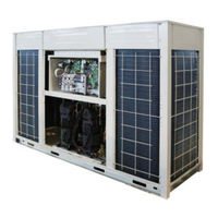
AUX ARV-H670/5R1B Technical Manual (149 pages)
DC Inverter
Brand:
AUX
| Category:
Air Conditioner
| Size: 7 MB
Table of Contents
Part1 General Information
2
Table of Contents
2
Energy Saving Technology
4
Features
4
Convenience and Comfort
5
Reliable & Stable
7
Intelligent Control
8
External Appearance
9
Outdoor Unit
9
Indoor Units
9
Indoor Unit
10
Nomenclatures
10
Outdoor Unit
10
Part2 Specification & Performance
11
Specifications
12
Dimensions
16
Piping Diagrams
18
Refrigeration Cycle Diagram
18
Refrigerant Circuit
22
Wire Diagrams
24
Operation Limits
27
Capacity Table
28
Correction of Capacity
82
Control Discipline
85
Electric Characteristic
90
Sound Level
91
Part3 Installation
92
Explode View
92
Installation Procedure
93
Preparation and Tools before Installation
93
Preparation on Installation
93
Installation Location and Foundation
95
Installation of Outdoor Unit
95
Maintenance and Ventilation Space for Outdoor Unit
95
Installation of Outdoor Unit
97
Connection Ratio of Capacity
99
Installation Notice
99
Installation Ofrefrigerant Pipe
99
Connection Schematic Diagram of Pipe
100
Type and Physical Dimension of Branch Pipe
104
Connection and Welding of Pipe
107
Gas Tightness Test
107
Vacuum Drying
108
Additional Refrigerant
111
Operation Procedure
111
Recharging R410A Refrigerant
111
Steps for Recharging Refrigerant
111
Insulation
112
Caution and Notice
114
Electrical Connection
114
Wiring Diagram of Indoor Unit and Outdoor Unit
115
Communication Line Connection
116
Iring
117
Part4 Commissioning
118
Commissioning of Trial Run
119
Inspection and Confirmation before Commissioning
119
Preparation before Start up
119
Preparatory Work
119
Refrigerant Leakage Caution
119
Commissioning Procedure
121
Cooling Commissioning Procedure
121
Heating Commissioning Procedure
122
Check the Outdoor Unit Capacity Setting
123
Check the Outdoor Unit Type Setting
123
DIP Switch Setting
123
The Quantity of Outdoor and Indoor Unit Lock Setting
123
Table of Contents
124
Inspection in Advance
125
Error Code Indication
126
Indoor Unit Error Code Display
126
Outdoor Unit Error Code Display
128
Indoor Unit Error Code Explanation
129
Outdoor Unit Error Code Explanation
130
Temperature or Pressure Sensor Failure
130
Electric Control System Failure and Protection
131
Refrigerant System Protection
131
Symbol Description
133
Appendix
134
Relation between Temperature Sensor of Compressor and Resistance
134
Elation between Temperature Sensor of Coil Pipe and Resistance
138
Advertisement
Advertisement
Related Products
AUX ARV-H615/5R1B
AUX ARV-H610/SR1MV
AUX ARV-H610/SR1MV-S
AUX ARV-H620/5R1I
AUX ARV-H670/5R1I
AUX ARV-H730/5R1B
AUX ARV-H280/SR1MV
AUX ARV-H560/SR1MV
AUX ARV-H500/SR1MV-S
AUX ARV-H850/5R1I
AUX Categories
Air Conditioner
Heat Pump
Inverter
Remote Control
Controller
More AUX Manuals
Login
Sign In
OR
Sign in with Facebook
Sign in with Google
Upload manual
Upload from disk
Upload from URL