Sign In
Upload
Manuals
Brands
autosen Manuals
Monitor
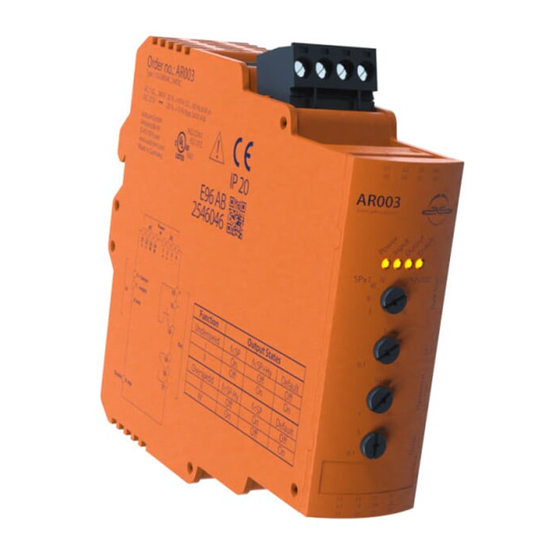
AR003
User Manuals: autosen AR003 Monitoring Relay
Manuals and User Guides for autosen AR003 Monitoring Relay. We have
1
autosen AR003 Monitoring Relay manual available for free PDF download: Operating Instructions Manual
autosen AR003 Operating Instructions Manual (64 pages)
Speed monitor
Brand:
autosen
| Category:
Monitor
| Size: 1 MB
Table of Contents
Deutsch
2
Table of Contents
2
Vorbemerkung
4
1�1 Verwendete Symbole
4
1�2 Verwendete Warnhinweise
4
Sicherheitshinweise
5
2�1 Allgemein
5
2�2 Zielgruppe
5
2�3 Elektrischer Anschluss
5
2�4 Bedienung
6
2�5 Einbauort
6
2�6 Gehäusetemperatur
6
2�7 Eingriffe in das Gerät
6
Bestimmungsgemäße Verwendung
7
Bedien- und Anzeigeelemente
8
4�1 Leds
8
4�2 Potentiometer
8
Montage
10
5�1 Montage des Gerätes
10
5�1�1 Gerät Entfernen
10
5�2 Montage der Sensoren
10
Elektrischer Anschluss
11
6�1 Anschlusszubehör
11
6�2 Klemmenbelegung
11
6�3 Spannungsversorgung (Power)
12
6�3�1 AC-Versorgung
12
6�3�2 DC-Versorgung
12
6�4 Eingänge
13
6�4�1 Anschluss des Sensors
13
6�4�2 Enable-Eingang
13
6�5 Ausgänge
14
6�5�1 Relaisausgang
14
6�5�2 Transistorausgang
14
Einstellungen
15
7�1 Frequenzbereich und Schaltfunktion (Function)
15
7�1�1 Frequenzbereich (Spx1/Spx100)
15
7�1�2 Schaltfunktion I
15
7�2 Schaltpunkt
16
7�3 Hysterese (Hysteresis)
16
7�4 Anlaufüberbrückung (Delay)
16
7�5 Schaltdiagramm
17
7�5�1 mit Anlaufüberbrückung und Gekoppelten Spannungsversorgungen �17
17
7�5�2 mit Anlaufüberbrückung und Antriebsgekoppeltem Enable-Signal
18
Maßzeichnung
19
Technische Daten
19
9�1 Zulassungen/Normen
20
Fehlerbehebung
21
Wartung, Instandsetzung, Entsorgung
21
11�1 Wartung
21
11�2 Reinigen der Gehäuseoberfläche
21
11�3 Instandsetzung
21
11�4 Entsorgung
21
English
22
Preliminary Note
24
1�1 Symbols Used
24
1�2 Warning Signs Used
24
Safety Instructions
25
2�1 General
25
2�2 Target Group
25
2�3 Electrical Connection
25
2�4 Handling
26
2�5 Installation Location
26
2�6 Housing Temperature
26
2�7 Tampering with the Device
26
Functions and Features
27
Operating and Display Elements
28
4�1 Leds
28
4�2 Potentiometer
29
Installation
30
5�1 Installation of the Device
30
5�1�1 Remove the Device
30
5�2 Mounting of the Sensors
30
Electrical Connection
31
6�1 Connection Accessories
31
6�2 Terminal Connection
31
6�3 Voltage Supply (Power)
32
6�3�1 AC Supply
32
6�3�2 DC Supply
32
6�4 Inputs
32
6�4�1 Connection of the Sensor
32
6�4�2 Enable Input
33
6�5 Outputs
33
6�5�1 Relay Output
33
6�5�2 Transistor Output
33
Settings
34
7�1 Frequency Range and Switching Function (Function)
34
7�1�1 Frequency Range (Spx1/Spx100)
34
7�1�2 Switching Function I
34
7�2 Switch Point
35
7�3 Hysteresis
35
7�4 Start-Up Delay
36
7�5 Switching Diagram
37
7�5�1 with Start-Up Delay and Coupled Voltage Supplies
37
7�5�2 with Start-Up Delay and Enable Signal Coupled to the Motor
38
Scale Drawing
39
Technical Data
39
9�1 Approvals/Standards
40
Maintenance, Repair, Disposal
41
11�1 Maintenance
41
11�2 Cleaning the Housing Surface
41
11�3 Repair
41
11�4 Disposal
41
Troubleshooting
41
Français
42
Remarques Préliminaires
44
1�1 Symboles Utilisés
44
1�2 Avertissements Utilisés
44
Consignes de Sécurité
45
2�1 Remarques Générales
45
2�2 Cible
45
2�3 Raccordement Électrique
45
2�4 Manipulation
46
2�5 Lieu de Montage
46
2�6 Température du Boîtier
46
2�7 Interventions Sur L'appareil
46
Fonctionnement Et Caractéristiques
47
Eléments de Service Et D'indication
48
4�1 Led
48
4�2 Potentiomètre
49
Montage
50
5�1 Montage de L'appareil
50
5�1�1 Demontage de L'appareil
50
5�2 Montage des Capteurs
50
Raccordement Électrique
51
6�1 Accessoires de Raccordement
51
6�2 Raccordement des Bornes
51
6�3 Alimentation en Tension (Power)
52
6�3�1 Alimentation
52
6�3�2 Alimentation
52
6�4 Entrées
53
6�4�1 Raccordement du Capteur
53
6�4�2 Entrée Enable
53
6�5 Sorties
54
6�5�1 Sortie Relais
54
6�5�2 Sortie Transistor
54
Réglages
55
7�1 Gamme de Fréquence Et Fonction de Commutation (Function)
55
7�1�1 Gamme de Fréquence (Spx1/Spx100)
55
7�1�2 Fonction de Commutation I
55
7�2 Seuil de Commutation
56
7�3 Hystérésis (Hysteresis)
56
7�4 Temporisation de Démarrage (Delay)
57
7�5 Diagramme de Commutation
58
Plées
58
L'entraînement
59
Données Techniques
60
9�1 Homologations/Normes
61
Schéma D'encombrement
60
Correction D'erreurs
62
Entretien, Réparation Et Élimination
62
11�1 Entretien
62
11�2 Nettoyage de la Surface du Boîtier
62
11�3 Réparation
62
11�4 Elimination
62
Advertisement
Advertisement
Related Products
autosen AG002
autosen AG001
autosen AR005
autosen AP008
Autosen AI812
Autosen AP017
Autosen AP019
Autosen AL001
autosen AS005
autosen AU015
autosen Categories
Accessories
Security Sensors
Measuring Instruments
Monitor
Transmitter
More autosen Manuals
Login
Sign In
OR
Sign in with Facebook
Sign in with Google
Upload manual
Upload from disk
Upload from URL